E3X-NA41 Omron, E3X-NA41 Datasheet - Page 14
E3X-NA41
Manufacturer Part Number
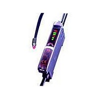
E3X-NA41
Description
PNP GEN PURPOSE FO AMP
Manufacturer
Omron
Series
E3X-NAr
Type
Standard Fiber Optic Sensorr
Specifications of E3X-NA41
Output Type
PNP
Amplifier Type
Standard
Voltage - Supply
12 V ~ 24 V
Current - Supply
35mA
Mounting Type
DIN Rail
Sensor Output
PNP LO/DO
Length/height, External
31.5mm
Sensor Input
Fiber Optic
External Width
10mm
Supply Voltage Max
24V
External Depth
64.3mm
Switch Terminals
Wire Leaded
Supply Voltage Min
12V
Rohs Compliant
Yes
Fiber Optic Sensor Type
Standard Fiber Optic Sensor
Lead Free Status / RoHS Status
Lead free / RoHS Compliant
Lead Free Status / RoHS Status
Lead free / RoHS Compliant, Lead free / RoHS Compliant
Other names
E3XNA41
Available stocks
Company
Part Number
Manufacturer
Quantity
Price
Company:

Part Number:
E3X-NA41
Manufacturer:
AVAGO
Quantity:
11 130


14
E3X-SD/-NA
Amplifier Units with Connectors
● Mounting
Mounting Connectors
1. Insert the Master or Slave Connector into the Amplifier Unit
2. Join Amplifier Units together as required after all the Master
3. Attach the stickers (provided as accessories) to the sides of
Note: Attach the stickers to the sides with grooves.
Removing Connectors
1. Slide the slave Amplifier Unit for which the Connector is to
2. After the Amplifier Unit has been separated, press down on
until it clicks into place.
and Slave Connectors have been inserted.
Master and Slave Connectors that are not connected to
other Connectors.
be removed away from the rest of the group.
the lever on the Connector and remove it. (Do not attempt
to remove Connectors without separating them from other
Amplifier Units first.)
Sticker
Insert
Press down
Sticker
Remove
Lever
Mounting End Plate (PFP-M)
Depending on how it is mounted, an Amplifier Unit may move
during operation. In this case, use an End Plate.
Before mounting an End Plate, remove the clip from the
master Amplifier Unit using a nipper or similar tool.
The clip can also be removed using the following mechanism,
which is incorporated in the construction of the section
underneath the clip.
1. Insert the clip to be removed into the slit underneath the clip
2. Remove the clip by rotating the Amplifier Unit.
Pull Strengths for Connectors (Including Cables)
E3X-CN11: 30 N max.
E3X-CN12: 12 N max.
on another Amplifier Unit.
Rotate
Clip
Related parts for E3X-NA41
Image
Part Number
Description
Manufacturer
Datasheet
Request
R

Part Number:
Description:
SENSOR PHOTOAMP FIBER 2M CBL
Manufacturer:
Omron
Datasheet:

Part Number:
Description:
CONN READY NPN GEN PURPOSE FO
Manufacturer:
Omron
Datasheet:
Part Number:
Description:
CONN READY PNP GEN PURPOSE FO
Manufacturer:
Omron
Datasheet:
Part Number:
Description:
PNP GREEN LED GEN PURPOSE FOA
Manufacturer:
Omron
Datasheet:
Part Number:
Description:
AMANUAL FA NPN RED M8 CONN
Manufacturer:
Omron
Datasheet:

Part Number:
Description:
NPN GEN PURPOSE FO AMP
Manufacturer:
Omron
Datasheet:

Part Number:
Description:
AUTOTUNE NPN
Manufacturer:
Omron
Datasheet:
Part Number:
Description:
AUTOTUNE NPN TMR REMOTE TCH
Manufacturer:
Omron
Datasheet:
Part Number:
Description:
AUTOTUNE PNP TMR REMOTE TCH
Manufacturer:
Omron
Datasheet:

Part Number:
Description:
PREWIRED DIGITAL NPN FO AMP
Manufacturer:
Omron
Datasheet:

Part Number:
Description:
G6S-2GLow Signal Relay
Manufacturer:
Omron Corporation
Datasheet:
Part Number:
Description:
Compact, Low-cost, SSR Switching 5 to 20 A
Manufacturer:
Omron Corporation
Datasheet:
Part Number:
Description:
Manufacturer:
Omron Corporation
Datasheet: