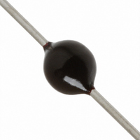
V180MA1A Littelfuse Inc, V180MA1A Datasheet - Page 4

V180MA1A
Manufacturer Part Number
V180MA1A
Description
VARISTOR 180V 1MA .60J 3MM AXIAL
Manufacturer
Littelfuse Inc
Specifications of V180MA1A
Varistor Voltage
180V
Current-surge
100A
Number Of Circuits
1
Maximum Ac Volts
105VAC
Maximum Dc Volts
144VDC
Energy
0.60J
Package / Case
Axial
Suppressor Type
Varistor
Peak Surge Current @ 8/20µs
100A
Clamping Voltage Vc Max
310V
Peak Energy (10/1000us)
0.6J
Voltage Rating Vdc
144V
Voltage Rating Vac
105V
Product
MOV
Voltage Rating Dc
144 V
Voltage Rating Ac
105 V
Clamping Voltage
310 V
Peak Surge Current
100 A
Capacitance
27 pF
Operating Temperature Range
- 55 C to + 85 C
Mounting
Radial
Dimensions
3 mm Dia.
Termination Style
Axial
Lead Free Status / RoHS Status
Lead free / RoHS Compliant
Lead Free Status / RoHS Status
Lead free / RoHS Compliant, Lead free / RoHS Compliant
Other names
F2295
V180MA1A
V180MA1A
Varistor Products
Transient V-I Characteristics Curves
MA Varistor Series
Axial Lead
130
FIGURE 3. CLAMPING VOLTAGE FOR V18MA1A/S - V100MA4A/S
FIGURE 5. CLAMPING VOLTAGE FOR V18MA1B - V100MA4B
600
500
400
300
200
100
800
600
400
300
200
150
100
90
80
70
60
50
40
30
20
80
60
40
30
20
10
10
-3
-2
O
MAX CLAMPING VOLTAGE
DISC SIZE 3mm
18 TO 100V
T
100
MAX CLAMPING VOLTAGE
DISC SIZE 3mm
18 TO 100V
T
A
1
90
50
10
A
= -55
= -55
10
o
-2
o
C TO 85
C TO 85
N(DC)
N(DC)
10
T
T
-1
1
PEAK AMPERES (A)
10
o
RATING
T
o
RATING
C
C
-1
2
PEAK AMPERES (A)
FIGURE 2. PEAK PULSE CURRENT TEST WAVEFORM
10
10
0
0
V100MA4A/S
V82MA3A/S
TIME
V68MA3A/S
V18MA1A/S
10
V18MA1B
V22MA1A/S
V56MA2A/S
V22MA1B
1
V27MA1B
V27MA1A/S
V33MA1B
V33MA1A/S
10
V39MA2B
V47MA2B
V39MA2A/S
V56MA2B
1
V100MA4B
V82MA3B
V68MA3B
V47MA2A/S
10
2
w w w . l i t t e l f u s e . c o m
Example: For an 8/20µs Current Waveform:
20µs = T
8µs = T
O
T
T
T = Time From 10% to 90% of Peak
1
1
2
10
10
= Virtual Origin of Wave
= Virtual Front time = 1.25 • t
= Virtual Time to Half Value (Impulse Duration)
2
3
1
2
= Virtual Front Time
= Virtual Time to Half Value
FIGURE 6. CLAMPING VOLTAGE FOR V120MA2B - V430MA7B
FI GURE 4. CLAMPING VOLTAGE FOR V120MA1A/S -
4,000
3,000
2,000
1,000
4,000
2,000
1,500
1,000
900
800
700
600
500
400
300
200
100
800
600
400
200
100
10
10
-2
-3
MAXIMUM CLAMPING VOLTAGE
DISC SIZE 3mm
120 TO 430V
T
MAX CLAMPING VOLTAGE
DISC SIZE 3mm
120 TO 430V
T
A
A
= -55
= -55
V430MA3A
10
o
-2
o
C TO 85
C TO 85
10
N(DC)
N(DC)
-1
10
o
o
PEAK AMPERES (A)
C
PEAK AMPERES (A)
-1
RATING
C
RATING
10
10
0
0
V430MA3A
V390MA3A
V330MA2A
10
V270MA2A
V120MA1A/S
1
V150MA1A
V220MA2A
V180MA1A
10
1
10
2
V430MA7B
V390MA6B
V330MA5B
V270MA4B
V220MA4B
V180MA3B
V150MA2B
V120MA2B
10
10
2
3


