V180MA1A Littelfuse Inc, V180MA1A Datasheet - Page 2
V180MA1A
Manufacturer Part Number
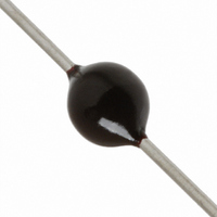
V180MA1A
Description
VARISTOR 180V 1MA .60J 3MM AXIAL
Manufacturer
Littelfuse Inc
Specifications of V180MA1A
Varistor Voltage
180V
Current-surge
100A
Number Of Circuits
1
Maximum Ac Volts
105VAC
Maximum Dc Volts
144VDC
Energy
0.60J
Package / Case
Axial
Suppressor Type
Varistor
Peak Surge Current @ 8/20µs
100A
Clamping Voltage Vc Max
310V
Peak Energy (10/1000us)
0.6J
Voltage Rating Vdc
144V
Voltage Rating Vac
105V
Product
MOV
Voltage Rating Dc
144 V
Voltage Rating Ac
105 V
Clamping Voltage
310 V
Peak Surge Current
100 A
Capacitance
27 pF
Operating Temperature Range
- 55 C to + 85 C
Mounting
Radial
Dimensions
3 mm Dia.
Termination Style
Axial
Lead Free Status / RoHS Status
Lead free / RoHS Compliant
Lead Free Status / RoHS Status
Lead free / RoHS Compliant, Lead free / RoHS Compliant
Other names
F2295
V180MA1A
V180MA1A


Varistor Products
MA Varistor Series
Absolute Maximum Ratings
Continuous:
Transient:
Operating Ambient Temperature Range (T A ) . . . . . . . . . . . . . . . . . . . . . . . . . . . . . . . . . . . . . . . . . . . . . . . . . . . . . . . . . . . . . . . . . . -55 to 85
Storage Temperature Range (T STG ) . . . . . . . . . . . . . . . . . . . . . . . . . . . . . . . . . . . . . . . . . . . . . . . . . . . . . . . . . . . . . . . . . . . . . . . -55 to 125
Temperature Coefficient (αV) of Clamping Voltage (V C ) at Specified Test Current . . . . . . . . . . . . . . . . . . . . . . . . . . . . . . . . . . . . . . <0.01
Hi-Pot Encapsulation (Isolation Voltage Capability) . . . . . . . . . . . . . . . . . . . . . . . . . . . . . . . . . . . . . . . . . . . . . . . . . . . . . . . . . . . . . . . 1000
Insulation Resistance
CAUTION: Stresses above those listed in “Absolute Maximum Ratings” may cause permanent damage to the device. This is a stress only rating and operation of the device
at these or any other conditions above those indicated in the operational sections of this specification is not implied.
Device Ratings and Specifications
Axial Lead
V18MA1A
V18MA1B
V18MA1S
V22MA1A
V22MA1B
V22MA1S
V27MA1A
V27MA1B
V27MA1S
V33MA1A
V33MA1B
V33MA1S
V39MA2A
V39MA2B
V39MA2S
V47MA2A
V47MA2B
V47MA2S
V56MA2A
V56MA2B
V56MA2S
V68MA3A
V68MA3B
V68MA3S
V82MA3A
V82MA3B
V82MA3S
Steady State Applied Voltage:
AC Voltage Range (V M(AC)RMS ) . . . . . . . . . . . . . . . . . . . . . . . . . . . . . . . . . . . . . . . . . . . . . . . . . . . . . . . . . . . . . . . . . . . . . . . . 9 to 264
DC Voltage Range (V M(DC) ) . . . . . . . . . . . . . . . . . . . . . . . . . . . . . . . . . . . . . . . . . . . . . . . . . . . . . . . . . . . . . . . . . . . . . . . . . . . 13 to 365
Peak Pulse Current (I TM )
For 8/20µs Current Wave (See Figure 2) . . . . . . . . . . . . . . . . . . . . . . . . . . . . . . . . . . . . . . . . . . . . . . . . . . . . . . . . . . . . . . . . . . 40 to 100
Single Pulse Energy Range
For 10/1000µs Current Wave (W TM ) . . . . . . . . . . . . . . . . . . . . . . . . . . . . . . . . . . . . . . . . . . . . . . . . . . . . . . . . . . . . . . . . . . . . . 0.06 to 1.7
(Dielectric must withstand indicated DC voltage for one minute per MIL-STD 202, Method 301) . . . . . . . . . . . . . . . . . . . . . . . . . . . . . . . . . . . . . . .
NUMBER
PART
128
BRAND
47B
47S
82A
18A
18B
18S
22A
22B
22S
27A
27B
27S
33A
33B
33S
39A
39B
39S
47A
56A
56B
56S
68A
68B
68S
82B
82S
V
V
M(AC)
CONTINUOUS
RMS
(V)
10
10
10
14
14
13
17
17
18
20
20
22
25
25
27
30
30
32
35
35
38
40
40
45
50
50
9
For ratings of individual members of a series, see Device Ratings and Specifications chart
MAXIMUM RATINGS (85
V
M(DC)
V
(V)
13
14
14
15
18
18
19
22
22
23
26
26
28
31
31
34
38
38
40
45
45
48
56
56
60
66
66
DC
(10/1000µs)
ENERGY
W
0.06
0.07
0.06
0.09
0.10
0.09
0.10
0.11
0.10
0.13
0.15
0.14
0.16
0.18
0.17
0.19
0.21
0.19
0.23
0.25
0.23
0.26
0.30
0.27
0.33
0.37
0.34
(J)
TM
TRANSIENT
o
C)
CURRENT
(8/20µs)
w w w . l i t t e l f u s e . c o m
PEAK
I
(A)
40
40
40
40
40
40
40
40
40
40
40
40
40
40
40
40
40
40
40
40
40
40
40
40
40
40
40
TM
VARISTOR VOLTAGE AT
29.5
29.5
MIN
(V)
14
15
15
16
19
19
21
24
24
26
31
35
35
37
42
42
44
50
50
54
61
61
65
73
73
1mA DC TEST
CURRENT
V
N(DC)
(V)
18
18
18
22
22
22
27
27
27
33
33
33
39
39
39
47
47
47
56
56
56
68
68
68
82
82
82
SPECIFICATIONS (25
MAX
36.5
36.5
(V)
23
21
21
28
26
26
34
31
31
40
47
43
43
57
52
52
68
62
62
82
75
75
99
91
91
MAX CLAMPING
V
VOLTAGE
C
(8/20µs)
AT 2.0A
(V)
117
108
117
138
127
138
163
150
163
V
49
44
49
55
51
55
67
59
67
73
67
73
86
79
86
99
90
99
C
o
C)
TYPICAL
CAPACI-
f = 1MHz
TANCE
(pF)
550
550
550
410
410
410
370
370
370
300
300
300
250
250
250
210
210
210
180
180
180
150
150
150
120
120
120
MA SERIES
1000
UNITS
%/
MΩ
O
O
V
V
A
V
J
C
C
O
C
Related parts for V180MA1A
Image
Part Number
Description
Manufacturer
Datasheet
Request
R

Part Number:
Description:
FUSEHOLDER 20A MINI INLINE CRIMP
Manufacturer:
Littelfuse Inc
Datasheet:

Part Number:
Description:
FUSEHOLDER BODY ATO INLINE PNLMT
Manufacturer:
Littelfuse Inc
Datasheet:

Part Number:
Description:
FUSE 2A 63V FAST 1206
Manufacturer:
Littelfuse Inc
Datasheet:
Part Number:
Description:
FUSE 1.25A 63V FAST 1206
Manufacturer:
Littelfuse Inc
Datasheet:
Part Number:
Description:
FUSE .250A 125V FAST 1206
Manufacturer:
Littelfuse Inc
Datasheet:
Part Number:
Description:
FUSE 4A 32V FAST 1206
Manufacturer:
Littelfuse Inc
Datasheet:
Part Number:
Description:
FUSE 1.75A 63V FAST 1206
Manufacturer:
Littelfuse Inc
Datasheet:

Part Number:
Description:
FUSE 1A 32V FST 0603 LEADFREE TR
Manufacturer:
Littelfuse Inc
Datasheet:

Part Number:
Description:
FUSE 1A 32V FAST SLIM 0402
Manufacturer:
Littelfuse Inc
Datasheet:

Part Number:
Description:
FUSE 2A 125V FAST NANO2 SMD
Manufacturer:
Littelfuse Inc
Datasheet:

Part Number:
Description:
FUSE .250A 125V FAST NANO2 SMD
Manufacturer:
Littelfuse Inc
Datasheet:

Part Number:
Description:
FUSE .500A 125V FAST NANO2 SMD
Manufacturer:
Littelfuse Inc
Datasheet:

Part Number:
Description:
FUSE 1.5A 125V FAST NANO2 SMD
Manufacturer:
Littelfuse Inc
Datasheet:

Part Number:
Description:
FUSE 4A 125V FAST NANO2 SMD
Manufacturer:
Littelfuse Inc
Datasheet:

Part Number:
Description:
FUSE 1A 125V FAST NANO2 SMD
Manufacturer:
Littelfuse Inc
Datasheet: