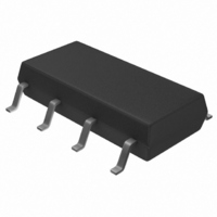
TISP61089BDR Bourns Inc., TISP61089BDR Datasheet - Page 3

TISP61089BDR
Manufacturer Part Number
TISP61089BDR
Description
SURGE SUPP SLIC PROG HV 8-SOP
Manufacturer
Bourns Inc.
Datasheet
1.TISP61089BDR-S.pdf
(20 pages)
Specifications of TISP61089BDR
Package / Case
8-SOIC (3.9mm Width)
Voltage - Breakover
*
Voltage - Off State
170V
Current - Peak Pulse (10 X 1000µs)
30A
Current - Hold (ih)
150mA
Number Of Elements
2
Capacitance
100pF
Applications
SLIC
Number Of Circuits
2
Voltage - Working
-100V
Voltage - Clamping
-112V
Technology
Mixed Technology
Breakover Current Ibo Max
6.5 A
Rated Repetitive Off-state Voltage Vdrm
170 V
Off-state Leakage Current @ Vdrm Idrm
0.005 mA
Holding Current (ih Max)
150 mA
Mounting Style
SMD/SMT
Power (watts)
-
Lead Free Status / RoHS Status
Lead free / RoHS Compliant
Available stocks
Company
Part Number
Manufacturer
Quantity
Price
Part Number:
TISP61089BDR
Manufacturer:
BOURNS/伯恩斯
Quantity:
20 000
Company:
Part Number:
TISP61089BDR-S
Manufacturer:
LITTLEFUSE
Quantity:
4 114
Company:
Part Number:
TISP61089BDR-S
Manufacturer:
Bourns Inc.
Quantity:
31 562
Part Number:
TISP61089BDR-S
Manufacturer:
BOURNS/伯恩斯
Quantity:
20 000
NOTES: 4. The diode forward recovery and the thyristor gate impulse breakover (overshoot) are not strongly dependent of the gate supply
Recommended Operating Conditions
Electrical Characteristics, T J = 25
Thermal Characteristics
V
R
V
V
GK(BO)
I
C
V
GKS
θ
C
I
R
V
FRM
(BO)
I
I
GT
JA
GT
D
H
KA
G
S
F
TISP61089B High Voltage Ringing SLIC Protector
5. These capacitance measurements employ a three terminal capacitance bridge incorporating a guard circuit. The unmeasured
TISP61089B gate decoupling capacitor
TISP61089B series resistor for GR-1089-CORE first-level surge survival
TISP61089B series resistor for GR-1089-CORE first-level and second-level surge survival
TISP61089B series resistor for GR-1089-CORE intra-building port surge survival
TISP61089B series resistor for K.20, K.21 and K.45 coordination with a 400 V primary
protector
Peak forward recovery
Gate-cathode impulse
Parameter
Gate-cathode trigger
Gate reverse current
Gate trigger current
Cathode-anode off-
voltage value (V
device terminals are a.c. connected to the guard terminal of the bridge.
Breakover voltage
breakover voltage
state capacitance
Off-state current
Forward voltage
Junction to free air thermal resistance
Holding current
voltage
voltage
Parameter
GG
).
I
2/10 µs, I
I
I
V
2/10 µs, I
(see Note 4)
2/10 µs, I
V
I
f = 1 MHz, V
F
T
T
T
D
GG
= 5 A, t
= -1 A, di/dt = 1A/ms, V
= -3 A, t
= -3 A, t
= V
°
C (Unless Otherwise Noted)
= V
DRM
GK
TM
TM
F
w
Component
p(g)
p(g)
, V
= 100 A, di/dt = 80 A/µs, R
= V
= 200 µs
d
= -100 A, di/dt = -80 A/µs, R
= -100 A, di/dt = -80 A/µs, R
GK
= 1 V, I
≥ 20 µs, V
≥ 20 µs, V
GKRM
= 0
, V
G
KA
= 0, (see Note 5)
GG
GG
Test Conditions
GG
= 0
JESD51-2 environment, P
= -100 V
= -100 V
T
= -100 V
A
= 25 °C, EIA/JESD51-3 PCB, EIA/
Test Conditions
S
= 50 Ω, (see Note 4)
S
S
= 50 Ω, V
= 50 Ω, V
Customers should verify actual device performance in their specific applications.
GG
GG
TOT
= -100 V
= -100 V,
= 1.7 W
V
T
T
T
T
V
J
J
J
J
D
D
= 25 °C
= 85 °C
= 25 °C
= 85 °C
= -48 V
= -3 V
Specifications are subject to change without notice.
-150
100
Min
Min
Min
40
10
25
8
OCTOBER 2000 - REVISED JULY 2008
220
Typ
Typ
Typ
-112
Max
Max
Max
100
120
-50
-50
2.5
50
-5
12
-5
10
3
5
°C/W
Unit
Unit
Unit
mA
mA
nF
µA
µA
µA
µA
pF
pF
V
V
Ω
Ω
Ω
Ω
V
V
V


