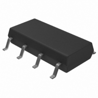
TISP61089BDR Bourns Inc., TISP61089BDR Datasheet - Page 13

TISP61089BDR
Manufacturer Part Number
TISP61089BDR
Description
SURGE SUPP SLIC PROG HV 8-SOP
Manufacturer
Bourns Inc.
Datasheet
1.TISP61089BDR-S.pdf
(20 pages)
Specifications of TISP61089BDR
Package / Case
8-SOIC (3.9mm Width)
Voltage - Breakover
*
Voltage - Off State
170V
Current - Peak Pulse (10 X 1000µs)
30A
Current - Hold (ih)
150mA
Number Of Elements
2
Capacitance
100pF
Applications
SLIC
Number Of Circuits
2
Voltage - Working
-100V
Voltage - Clamping
-112V
Technology
Mixed Technology
Breakover Current Ibo Max
6.5 A
Rated Repetitive Off-state Voltage Vdrm
170 V
Off-state Leakage Current @ Vdrm Idrm
0.005 mA
Holding Current (ih Max)
150 mA
Mounting Style
SMD/SMT
Power (watts)
-
Lead Free Status / RoHS Status
Lead free / RoHS Compliant
Available stocks
Company
Part Number
Manufacturer
Quantity
Price
Part Number:
TISP61089BDR
Manufacturer:
BOURNS/伯恩斯
Quantity:
20 000
Company:
Part Number:
TISP61089BDR-S
Manufacturer:
LITTLEFUSE
Quantity:
4 114
Company:
Part Number:
TISP61089BDR-S
Manufacturer:
Bourns Inc.
Quantity:
31 562
Part Number:
TISP61089BDR-S
Manufacturer:
BOURNS/伯恩斯
Quantity:
20 000
The telecommunications port R and T terminals may be tested simultaneously or individually. Figure 14 shows connection for simultaneous
(longitudinal) testing. Figure 15 shows the two connections necessary to individually test the R and T terminals during transverse testing.
The values of protector current are calculated by dividing the open-circuit generator voltage by the total circuit resistance. The total circuit
resistance is the sum of the generator fictive source resistance and the TISP61089B series resistor value. The starting point of this analysis is
to calculate the minimum circuit resistance for a test by dividing the generator open-circuit voltage by the TISP61089B rating. Subtracting the
generator fictive resistance from the minimum circuit resistance gives the lowest value of series resistance that can be used. This is repeated
for all test connections. As the series resistance must be a fixed value, the value used has to be the highest value calculated from all the
considered test connections. Where both 10/1000 and 2/10 waveshape testing occurs, the 10/1000 test connection gives the highest value of
minimum series resistance. Unless otherwise stated, the analysis assumes a -40 °C to +85 °C temperature range.
Table 1 shows the tests for this section. The peak TISP61089B current, I
the generator fictive source and the line feed, R
40 Ω. The TISP61089B rated current values at the various waveshapes are higher than those listed in Table 1. Used with the specified values
of R
Table 2 shows the 2/10 test used for this section. Columns 9 and 10 show the resultant currents for R
R
second-level conditions, the peak current will be 2x143 A, which may result in failure of the 2x120 A rated TISP61089B. However, if the testing
is done at or near 25 °C, the TISP61089B will survive with an R
NOTE:
NOTES: 1. Surge 3 may be used instead of Surge 1 and Surge 2.
‘1089 Section 4.5.6 - Test Connections
‘1089 Section 4.5.7 - First-Level Lightning Surge Testing
‘1089 Section 4.5.8 - Second-Level Lightning Surge Testing
S
Surge
Surge
of 40 Ω, the TISP61089B with survive this test. The 25 Ω value of R
S
#
1
2
3
4
5
#
1
, the TISP61089B will survive these tests.
TISP61089B High Voltage Ringing SLIC Protector
1. If the equipment contains a voltage-limiting secondary protector, the test is repeated at a voltage just below the threshold of
2. Surge 5 is applied to multiple line pairs up to a maximum of 12.
3. If the equipment contains a voltage-limiting secondary protector, each test is repeated at a voltage just below the threshold of
Waveshape
Waveshape
limiting.
limiting.
10/1000
10/1000
10/360
10/360
2/10
2/10
Open-circuit
Open-circuit
Voltage
Voltage
1000
1000
2500
1000
5000
600
V
V
Short-circuit
Short-circuit
Current
Current
S
, resistance values. Columns 9 and 10 show the resultant currents for R
100
100
100
500
500
Table 2. Second-Level Surge Current
25
A
A
Table 1. First-Level Surge Currents
+25, -25
+25, -25
+25, -25
+10, -10
+1, -1
Tests
+5, -5
Tests
S
No
No
of
of
value of 25 Ω as the 2/10 rating is 170 A at this temperature.
S
TM
Connections
Connections
is only intended to give first-level (Section 4.5.7) survival. Under
Transverse &
Transverse &
Transverse &
Longitudinal
Longitudinal
Longitudinal
Longitudinal
Longitudinal
Longitudinal
, is calculated by dividing the generator open voltage by the sum of
Test
Test
Customers should verify actual device performance in their specific applications.
Primary
Primary
Fitted
Fitted
No
No
No
No
No
No
S
Resistance
Resistance
Generator
Generator
values of 25 Ω and 40 Ω. Used with an
Specifications are subject to change without notice.
Source
Fictive
Source
Fictive
10
40
10
10
Ω
6
5
Ω Ω Ω Ω
OCTOBER 2000 - REVISED JULY 2008
R
R
s
2x143
s
2x19
2x29
2x29
2x83
2x15
19 &
29 &
29 &
S
= 25 Ω
= 25 Ω Ω Ω Ω
TISP61089B I
TISP61089B I
values of 25 Ω and
A
A
R
R
s
2x100
s
2x13
2x20
2x20
2x56
2x13
13 &
20 &
20 &
= 40 Ω
= 40 Ω Ω Ω Ω
TM
TM


