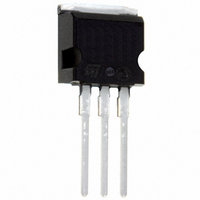
TLP200G-1 STMicroelectronics, TLP200G-1 Datasheet

TLP200G-1
Specifications of TLP200G-1
Available stocks
Related parts for TLP200G-1
TLP200G-1 Summary of contents
Page 1
Application Specific Discretes A.S.D. MAIN APPLICATIONS Any sensitive telecom equipment requiring protec- tion against lightning : Analog and ISDN line cards Main Distribution Frames Terminal and transmission equipment Gas-tube replacement DESCRIPTION The TLPxxM/G/G-1 series are tripolar transient surge arrestors ...
Page 2
TLPxxM/G/G-1 COMPLIES WITH THE FOLLOWING STANDARDS: CCITT K20 VDE0433 VDE0878 IEC-1000-4-5 FCC Part 68, lightning surge type A FCC Part 68, lightning surge type B BELLCORE TR-NWT-001089 FIRST LEVEL BELLCORE TR-NWT-001089 SECOND LEVEL CNET I31-24 TYPICAL APPLICATION Primary protection module ...
Page 3
TYPICAL APPLICATION ISDN: U interface protection TLPxxM/G/G-1 PARAMETER MEASUREMENT INFORMATION Symbol Description Peak pulse current Maximum peak on-state current TSM Leakage current Leakage current RM I Holding current H V Breakdown voltage BR V ...
Page 4
TLPxxM/G/G-1 THERMAL RESISTANCE Symbol Rth (j-c) Junction to case Rth (j-a) Junction to ambient ELECTRICAL CHARACTERISTICS BETWEEN TIP AND RING (T Type TLP140M/G/G-1 TLP200M/G/G-1 TLP270M/G/G-1 Note : bias, V RMS = 1V ...
Page 5
... Package Types PowerSO-10 TLP140M TLP200M TLP270M 2 D PAK TLP140G TLP200G TLP270G 2 I PAK TLP140G-1 TLP200G-1 TLP270G-1 ORDER CODE Tripolar Line Protection Breakdown Voltage ) TEST CIRCUIT: GO-NO GO TEST H R D.U.T. value by short circuiting the D.U. 10A, 10/1000 s. PP Marking TLP140M TLP200M TLP270M ...
Page 6
TLPxxM/G/G-1 Fig. 1: Maximum peak on-state current versus pulse duration. ITSM(A) 100 90 TIP or RING 80 vs GND t(s) 0 0.01 0 Fig. 3-1 :junction capacitance versus applied re- verse ...
Page 7
Fig. 5-1 : Breakover voltage measurement (TLP140M/G/G-1). Vbr/Vbr 2.6 2.4 TIP RING 2.2 2 1.8 1.6 1.4 TIP+ GND - 1.2 1 0.01 0 100 dV/dt Fig. 5-3 : Breakover voltage measurement (TLP270M/G/G-1). Vbo/Vbr 2.6 2.4 TIP RING ...
Page 8
TLPxxM/G/G-1 PACKAGE MECHANICAL DATA 2 D PAK Plastic 2.0 MIN. FLAT ZONE 2 FOOT-PRINT D PAK 16.90 10.30 3.70 8.90 8/14 REF. A Min. Typ. Max. Min. Typ. Max 4.30 ...
Page 9
PACKAGE MECHANICAL DATA 2 I PAK Plastic DIMENSIONS REF. Millimeters Min. Typ. Max. Min. Typ. Max. A 4.30 4.60 0.169 A1 2.49 2.69 0.098 B 0.70 0.93 0.028 B1 1.20 1.38 0.047 B2 1.25 1.40 0.049 0.055 C 0.45 0.60 ...
Page 10
TLPxxM/G/G-1 PACKAGE MECHANICAL DATA Power-SO10 DIMENSIONS REF. Millimeters Min. Typ. Max. Min. A 3.35 3.65 0.131 A1 0.00 0.10 0.00 B 0.40 0.60 0.0157 C 0.35 0.55 0.0137 D 9.40 9.60 0.370 ...
Page 11
FOOT PRINT Power-SO10 MOUNTING PAD LAYOUT RECOMMENDED Dimensions in millimeters SHIPPING TUBE B A Surface mount film taping : contact sales office HEADER SHAPE Dimensions in millimeters Length tube Quantity per tube TLPxxM/G/G-1 DIMENSIONS (mm) TYP ...
Page 12
TLPxxM/G/G-1 SOLDERING RECOMMENDATION The soldering process causes considerable ther- mal stress to a semiconductor component. This has to be minimized to assure a reliable and ex- tended lifetime of the device. The PowerSO-10 package can be exposed to a maximum ...
Page 13
SUBSTRATES AND MOUNTING INFORMATION The use of epoxy FR4 boards is quite common for surface mounting techniques, however, their poor thermal conduction compromises the outstanding thermal performance of the PowerSO- 10. Some methods to overcome this limitation are discussed below. ...
Page 14
... STMicroelectronics. Specifications mentioned in this publication are subject to change without notice. This publication supersedes and replaces all information previously supplied. STMicroelectronics products are not authorized for use as critical components in life support devices or systems without express written ap- proval of STMicroelectronics. ...


