DALC208SC6 STMicroelectronics, DALC208SC6 Datasheet
DALC208SC6
Specifications of DALC208SC6
Available stocks


Related parts for DALC208SC6


DALC208SC6 Summary of contents
Page 1
... March 2008 = 9 V per diode < 1 µA R Figure 1. Description The DALC208SC6 diode array is designed to protect components which are connected to data and transmission lines from over voltages caused by electrostatic discharge (ESD) or other transients rail-to-rail protection device also suited for overshoot and undershoot suppression on sensitive logic inputs ...
Page 2
Characteristics 1 Characteristics Table 1. Absolute maximum ratings (T Symbol IEC61000-4-2, air discharge V PP IEC61000-4-2, contact discharge V Peak reverse voltage per diode RRM V Reference voltage gap between V REF V max. Maximum operating signal input voltage In ...
Page 3
DALC208 Figure 3. Maximum non-repetitive peak forward current versus rectangular pulse duration (T I (A) FSM (ms 0.001 0.01 0.1 1 Figure 5. Variation of leakage current versus junction ...
Page 4
... Technical information 2 Technical information 2.1 Surge protection The DALC208SC6 is particularly optimized to perform surge protection based on the rail to rail topology. The clamping voltage REF2 REF1 F with forward drop voltage According to the curve clamping diode is typically R For an IEC 61000-4-2 surge Level 4 (Contact Discharge: V ...
Page 5
... REF2 as possible to avoid over voltages due to parasitic phenomena. See It’s often harder to connect the power supply near to the DALC208SC6 unlike the ground thanks to the ground plane that allows a short connection. To ensure the same efficiency for positive surges when the connections can’t be short ...
Page 6
... Figure 11. Remaining voltage after the DALC208SC6 during positive ESD surge Important A precaution to take is to put the protection device as close as possible to the disturbance source (generally the connector). Note: The measurements have been done with the DALC208SC6 in open circuit. 6/14 Figure 10. ESD behavior: measurement Vcl+ POSITIVE SURGE t ...
Page 7
... Square Pulse Line 2 Generator 5KHz DALC208SC6 Figure 14 shows the measurement circuit used to quantify the crosstalk effect in a classical digital application. time of 5 ns, the impact on the disturbed line is less than 100mV peak to peak. No data disturbance was noted on the concerned line. The same results were obtained with falling edges ...
Page 8
... As the DALC208SC6 is designed to protect high speed data lines, it must ensure a good transmission of operating signals. The attenuation curve give such an information. Figure 18 shows that the DALC208SC6 is well suitable for data line transmission up to 100 Mbit/s while it works as a filter for undesirable signals such as GSM carrier (900 MHz). ...
Page 9
... Application examples Figure 19. Video line protection +Vcc DALC 100nF 5 15 +Vcc 100nF Figure 20. T1/E1 protection Tx SMP75-8 +Vcc DALC 208 100nF Rx SMP75-8 Figure 22. Another way to connect the DALC208SC6 Pin N° 208 or COMPOSITE SYNC with GREEN VIDEO DDC (Display Data Channel) GROUND DALC ...
Page 10
... PSpice model 5 PSpice model Figure 23 shows the PSpice model of one DALC208SC6 cell. In this model, the diodes are defined by the PSpice parameters given in Figure 23. PSpice model of one DALC208SC6 cell Vref2 0.8nH 0.3 I/O Vref1 Note: This simulation model is available only for an ambient temperature of 27 °C. The simulations ...
Page 11
DALC208 Table 4. PSpice parameter Parameter BV CJO IBV IKF IS ISR POS 28.357E-3 118.78E-15 100E-12 0.3333 1.3334 2 0.68377 0.6 PSpice model D NEG 1000 5.6524E-9 472.3E-9 ...
Page 12
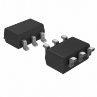
Package information 6 Package information ● Epoxy meets UL94 order to meet environmental requirements, ST offers these devices in ECOPACK packages. These packages have a lead-free second level interconnect. The category of second level interconnect is marked on ...
Page 13
... DALC208 7 Ordering information Table 6. Ordering information Order code DALC208SC6 8 Revision history Table 7. Document revision history Date Feb-2002 28-Oct-2004 20-Mar-2008 Marking Package DALC SOT23-6L Revision 5C Last update. SOT23-6L package dimensions change for reference “D” from 3.0 6 millimeters (0.118 inches) to 3.05 millimeters (0.120 inches). ...
Page 14
... Information in this document is provided solely in connection with ST products. STMicroelectronics NV and its subsidiaries (“ST”) reserve the right to make changes, corrections, modifications or improvements, to this document, and the products and services described herein at any time, without notice. All ST products are sold pursuant to ST’s terms and conditions of sale. ...