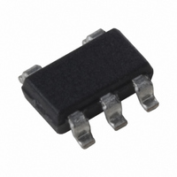
MIC5246-1.6BM5 TR Micrel Inc, MIC5246-1.6BM5 TR Datasheet - Page 8

MIC5246-1.6BM5 TR
Manufacturer Part Number
MIC5246-1.6BM5 TR
Description
IC REG LDO 150MA 1.6V SOT23-5
Manufacturer
Micrel Inc
Datasheet
1.MIC5246-1.6BM5_TR.pdf
(12 pages)
Specifications of MIC5246-1.6BM5 TR
Regulator Topology
Positive Fixed
Voltage - Output
1.6V
Voltage - Input
2.7 ~ 6 V
Voltage - Dropout (typical)
0.15V @ 150mA
Number Of Regulators
1
Current - Output
150mA
Current - Limit (min)
160mA
Operating Temperature
-40°C ~ 125°C
Mounting Type
Surface Mount
Package / Case
SOT-23-5, SC-74A, SOT-25
Lead Free Status / RoHS Status
Contains lead / RoHS non-compliant
Other names
MIC5246-1.6BM5TR
MIC5246-1.6BM5TR
MIC5246-1.6BM5TR
MIC5246
The actual power dissipation of the regulator circuit can be
determined using the equation:
Substituting P
conditions that are critical to the application will give the
maximum operating conditions for the regulator circuit. For
example, when operating the MIC5246-3.0BM5 at 50 C with
a minimum footprint layout, the maximum input voltage for a
set output current can be determined as follows:
The junction-to-ambient thermal resistance for the minimum
footprint is 235 C/W, from Table 1. The maximum power
dissipation must not be exceeded for proper operation. Using
the output voltage of 3.0V and an output current of 150mA,
the maximum input voltage can be determined. Because this
device is CMOS and the ground current is typically 100 A
over the load range, the power dissipation contributed by the
ground current is < 1% and can be ignored for this calculation.
Therefore, a 3.0V application at 150mA of output current can
accept a maximum input voltage of 5.4V in a SOT-23-5
package. For a full discussion of heat sinking and thermal
effects on voltage regulators, refer to the Regulator Thermals
section of Micrel’s Designing with Low-Dropout Voltage Regu-
lators handbook.
MIC5246
P
P
315mW = (V
315mW = V
810mW = V
V
P
D(max)
D
D(max)
IN(max)
= (V
IN
= 315mW
= 5.4V
D(max)
– V
125 C 5 C
IN
IN
IN
235 C/W
OUT
·150mA – 450mW
·150mA
– 3.0V) 150mA
for P
) I
OUT
0
D
and solving for the operating
+ V
IN
I
GND
8
Fixed Regulator Applications
Figure 1 shows a standard low-noise configuration with a
47k pull-up resistor from the error flag to the input voltage
and a pull-down capacitor to ground for the purpose of fault
indication.
Dual-Supply Operation
When used in dual supply systems where the regulator load
is returned to a negative supply, the output voltage must be
diode clamped to ground.
Figure 1. Low-Noise Fixed Voltage Application
V
IN
MIC5246-x.xBM5
1
2
3
47k
5
4
V
1 F
OUT
June 2000
Micrel


