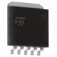
ST2L01K5R STMicroelectronics, ST2L01K5R Datasheet - Page 3

ST2L01K5R
Manufacturer Part Number
ST2L01K5R
Description
IC REGULATOR DUAL VOLT SPAK-SL
Manufacturer
STMicroelectronics
Datasheet
1.ST2L01K5R.pdf
(14 pages)
Specifications of ST2L01K5R
Regulator Topology
Positive Fixed and Adjustable
Voltage - Output
3.3V, 1.25 ~ 3 V
Voltage - Input
4.75 ~ 5.25 V
Voltage - Dropout (typical)
1.1V @ 1A
Number Of Regulators
2
Current - Output
1A
Current - Limit (min)
1A
Operating Temperature
0°C ~ 125°C
Mounting Type
Surface Mount
Package / Case
SPak (5 leads + Tab)
Lead Free Status / RoHS Status
Lead free / RoHS Compliant
Other names
497-2069-2
Available stocks
Company
Part Number
Manufacturer
Quantity
Price
TYPICAL APPLICATION CIRCUIT
Note:
C
C
For more details about Capacitors read the "Application Hints"
ELECTRICAL CHARACTERISTICS OF OUTPUT 1 (V
specified. Typical values are referred at T
Note 1: Low duty cycle pulse testing with Kelvin connections are required in order to maintain accurate data
Note 2: Dropout Voltage is defined as the minimum differential voltage between V
ured when the output voltage drops 1% below its nominal value.
Note 3: Transient response is defined with a step change in load from 10mA to 500mA as the time from the load step until the output voltage
reaches it’s minimum value.
Note 4: Minimum load current is defined as the minimum current required at the output in order for the output voltage to maintain regulation.
Note 5: Guaranteed by design, not tested in production.
Symbol
O1
I
, C
SVR1
V
I
eN1
V
V
t
I
SC1
V
V
V
value could be lowered down to 470nF Ceramic Capacitor (X7R);
OUT1
TR
O1
O1
I
O1
D1
I
O1
O1
O1
and C
Input Current
Output Voltage 1
Line Regulation 1
Load Regulation 1
Dropout Voltage 1
Transient Response
Current Limit 1
Minimum Load Current 1
Supply Voltage Rejection
Thermal Regulation
Output Noise
Temperature Stability
Long Term Stability
O2
capacitors must be located not more than 0.5" from the outputs pins of the device.
Parameter
I
T
I
T
V
I
I
(Note 2)
I
(Note 3, 5)
R
T
V
I
T
I
B= 10Hz to 10KHz
T
T
O1
O1
O
O
O
O1
(Note 5)
O
j
j
j
j
j
j
I
I
L
= 25°C
= 0 to 125°C
= 0 to 125°C
= 0 to 125°C
= 0 to 125°C
= 125°C, 1000Hrs
= 4.75 to 5.25V
= 5 0.25V
= 0.01 to 1A
= 1A
= 10 to 500mA t
= 1A,
= 0
= I
= 5mA to 1A
= 100 mA
O2
j
= 25°C, C
=0
Test Conditions
T
T
t
PULSE
j
j
= 0 to 125°C
= 0 to 125°C
(Note 5)
rise
I
T
V
(Note 1)
(Note 4)
= 30ms (Note 5)
= 1 F (Tantalum), C
(Note 5)
j
I
= t
I
= 0 to 125°C
= 4.75 to 5.25V
(Note 5)
=5V, I
fall
f
f
f
f
= 1 s
I
I
I
I
= 100Hz
= 1KHz
= 10KHz
= 100KHz
I
O1
and V
=10mA T
O
required to maintain regulation at V
j
= 0 to 125°C unless otherwise
O1
Min.
3.23
3.2
60
60
50
30
1
0
= C
V
O
= V
O1
Typ.
REF
3.3
3.3
0.1
1.1
0.1
0.5
0.3
<1
=1 F (X7R)
15
68
70
65
38
40
3
(1 +
Max.
R
R
3.37
3.4
1.3
12
1
2
28
6
)+I
O
ADJ
ST2L01
. It is meas-
R
%V
%V
%/W
Unit
Vrms
1
mA
mV
mV
mA
dB
V
V
A
s
3/14
O
O


