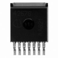
TLE4267G Infineon Technologies, TLE4267G Datasheet - Page 2

TLE4267G
Manufacturer Part Number
TLE4267G
Description
IC REGULATOR LDO 5V TO-263-7
Manufacturer
Infineon Technologies
Datasheet
1.TLE4267GM.pdf
(22 pages)
Specifications of TLE4267G
Package / Case
TO-263-7, D²Pak (7 leads + Tab), TO-263CA
Regulator Topology
Positive Fixed
Voltage - Output
5V
Voltage - Input
5.5 ~ 40 V
Voltage - Dropout (typical)
0.3V @ 400mA
Number Of Regulators
1
Current - Output
400mA (Max)
Current - Limit (min)
500mA
Operating Temperature
-40°C ~ 150°C
Mounting Type
Surface Mount
Number Of Outputs
1
Polarity
Positive
Input Voltage Max
40 V
Output Voltage
5 V
Output Type
Fixed
Dropout Voltage (max)
0.6 V at 400 mA
Output Current
400 mA
Load Regulation
50 mV
Voltage Regulation Accuracy
2 %
Maximum Operating Temperature
+ 125 C
Mounting Style
SMD/SMT
Minimum Operating Temperature
- 40 C
Lead Free Status / RoHS Status
Contains lead / RoHS non-compliant
Lead Free Status / RoHS Status
Lead free / RoHS Compliant, Contains lead / RoHS non-compliant
Other names
SP000011774
TLE4267G
TLE4267GINTR
TLE4267GNT
TLE4267GT
TLE4267G
TLE4267GINTR
TLE4267GNT
TLE4267GT
Available stocks
Company
Part Number
Manufacturer
Quantity
Price
Company:
Part Number:
TLE4267G
Manufacturer:
INF
Quantity:
9 999
Company:
Part Number:
TLE4267G
Manufacturer:
INFINEON
Quantity:
1 840
Part Number:
TLE4267G
Manufacturer:
INFINEON/英飞凌
Quantity:
20 000
Company:
Part Number:
TLE4267GM
Manufacturer:
SIEMENS
Quantity:
5 510
Part Number:
TLE4267GM
Manufacturer:
INFINEON/英飞凌
Quantity:
20 000
Application
The IC regulates an input voltage
voltage of
4.5 V). The reset delay can be set with an external capacitor. The device has two logic
inputs. A voltage of
Depending on the voltage on pin E6 the IC may be hold in active-state even if
to low level. This makes it simple to implement a self-holding circuit without external
components. When the device is turned off, the output voltage drops to 0 V and current
consumption tends towards 0 A.
Design Notes for External Components
The input capacitor
circuit consisting of lead inductance and input capacitance can be damped by a resistor
of approx. 1
regulating circuit. Stability is guaranteed at values of
the operating temperature range.
Circuit Description
The control amplifier compares a reference voltage, which is kept highly accurate by
resistance adjustment, to a voltage that is proportional to the output voltage and drives
the base of the series transistor via a buffer. Saturation control as a function of the load
current prevents any over-saturating of the power element.
The reset output RO is in high-state if the voltage on the delay capacitor
equal
greater than the reset threshold
discharge of the delay capacitor
reset output RO is set to low-level (see
range by dimensioning the capacitance of the external capacitor.
Data Sheet
V
UD
. The delay capacitance
V
Q
= 5.0 V. A reset signal is generated for an output voltage of
in series with
V
C
E2
I
is necessary for compensation of line influences. The resonant
> 4.0 V given to the E2-pin (e.g. by ignition) turns the device on.
C
I
. The output capacitor is necessary for the stability of the
C
V
V
D
C
I
RT
in the range of 5.5 V <
sets in and as soon as
D
. If the output voltage gets lower than
is charged with the current
Figure
2
6). The reset delay can be set within wide
22 F and an ESR of
V
V
I
CD
< 40 V to a nominal output
gets lower than
I
D
Rev. 2.5, 2007-03-20
for output voltages
C
V
D
Q
is greater or
TLE 4267
<
V
3
V
RT
V
E2
V
RT
within
a fast
LD
goes
(typ.
the


