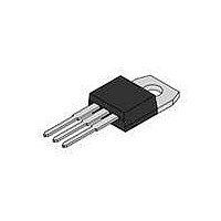
LM2931T-5.0G ON Semiconductor, LM2931T-5.0G Datasheet - Page 11

LM2931T-5.0G
Manufacturer Part Number
LM2931T-5.0G
Description
IC REG LDO 100MA 5V TO220AB
Manufacturer
ON Semiconductor
Datasheet
1.LM2931AZ-5.0RAG.pdf
(23 pages)
Specifications of LM2931T-5.0G
Regulator Topology
Positive Fixed
Voltage - Output
5V
Voltage - Input
Up to 40V
Voltage - Dropout (typical)
0.16V @ 100mA
Number Of Regulators
1
Current - Output
100mA
Operating Temperature
-40°C ~ 125°C
Mounting Type
Through Hole
Package / Case
TO-220-3 (Straight Leads)
Number Of Outputs
1
Polarity
Positive
Input Voltage Max
40 V
Output Voltage
5 V
Output Type
Fixed
Dropout Voltage (max)
0.2 V at 10 mA
Output Current
100 mA
Line Regulation
30 mV
Load Regulation
50 mV
Voltage Regulation Accuracy
5 %
Maximum Operating Temperature
+ 125 C
Mounting Style
Through Hole
Minimum Operating Temperature
- 40 C
Primary Input Voltage
40V
Output Voltage Fixed
5V
Dropout Voltage Vdo
600mV
No. Of Pins
3
Operating Temperature Range
-40°C To +150°C
Filter Terminals
Through Hole
Rohs Compliant
Yes
Current Rating
0.1A
Lead Free Status / RoHS Status
Lead free / RoHS Compliant
Current - Limit (min)
-
Lead Free Status / Rohs Status
Lead free / RoHS Compliant
Other names
LM2931T-5.0GOS
Available stocks
Company
Part Number
Manufacturer
Quantity
Price
Part Number:
LM2931T-5.0G
Manufacturer:
ON/安森美
Quantity:
20 000
at which the regulator output no longer maintains regulation
against further reductions in input voltage. Measured when
the output decreases 100 mV from nominal value at 14 V
input, dropout voltage is affected by junction temperature
and load current.
change in the input voltage. The measurement is made under
conditions of low dissipation or by using pulse techniques
such that the average chip temperature is not significantly
affected.
change in load current at constant chip temperature.
Dropout Voltage − The input/output voltage differential
Line Regulation − The change in output voltage for a
Load Regulation − The change in output voltage for a
300
250
200
150
100
50
80
70
60
50
40
30
0
Figure 27. SOT−223 Thermal Resistance and Maximum
0
0
Thermal Resistance and Maximum Power
Dissipation versus P.C.B. Copper Length
Power Dissipation vs. P.C.B. Copper Length
Vertically
Figure 26. 3−Pin and 5−Pin D
Mounted
5.0
Free Air
5.0
L, LENGTH OF COPPER (mm)
L, LENGTH OF COPPER (mm)
http://onsemi.com
10
10
DEFINITIONS
Minimum
Size Pad
P
D(max)
11
15
P
R
15
D(max)
qJA
for T
device dissipation for which the regulator will operate
within specifications.
delivered to the load.
output, with constant load and no input ripple, measured
over a specified frequency range.
accelerated life test conditions with the maximum rated
voltage listed in the devices electrical characteristics and
maximum power dissipation.
Maximum Power Dissipation − The maximum total
Bias Current − That part of the input current that is not
Output Noise Voltage − The rms AC voltage at the
Long−Term Stability − Output voltage stability under
for T
A
R
= 50°C
qJA
20
20
A
2.0 oz. Copper
= 50°C
L
L
Î Î Î Î
Î Î Î Î
Î Î Î Î
Î Î Î Î
Î Î Î
Î Î Î
Î Î Î
2.0 oz. Copper
2
PAK
25
25
L
L
30
30
1.8
1.6
1.4
1.2
1.0
0.8
0.6
0.4
0.2
0.0
3.5
3.0
2.5
2.0
1.5
1.0


