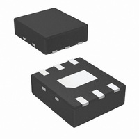
LP5900SD-3.0/NOPB National Semiconductor, LP5900SD-3.0/NOPB Datasheet - Page 8

LP5900SD-3.0/NOPB
Manufacturer Part Number
LP5900SD-3.0/NOPB
Description
IC REG LDO 150MA RF/ANLG 6-LLP
Manufacturer
National Semiconductor
Datasheet
1.LP5900SD-1.8EV.pdf
(12 pages)
Specifications of LP5900SD-3.0/NOPB
Regulator Topology
Positive Fixed
Voltage - Output
3V
Voltage - Input
Up to 5.5V
Voltage - Dropout (typical)
0.08V @ 150mA
Number Of Regulators
1
Current - Output
150mA (Max)
Operating Temperature
-40°C ~ 85°C
Mounting Type
Surface Mount
Package / Case
6-LLP
For Use With
LP5900SD-3.0EV - BOARD EVALUATION LP5900SD-3.0
Lead Free Status / RoHS Status
Lead free / RoHS Compliant
Current - Limit (min)
-
Other names
LP5900SD-3.0TR
Available stocks
Company
Part Number
Manufacturer
Quantity
Price
Part Number:
LP5900SD-3.0/NOPB
Manufacturer:
NS/国半
Quantity:
20 000
www.national.com
Application Hints
POWER DISSIPATION AND DEVICE OPERATION
The permissible power dissipation for any package is a mea-
sure of the capability of the device to pass heat from the power
source, the junctions of the IC, to the ultimate heat sink, the
ambient environment. Thus the power dissipation is depen-
dent on the ambient temperature and the thermal resistance
across the various interfaces between the die and ambient
air. As stated in
allowable power dissipation for the device in a given package
can be calculated using the equation:
The actual power dissipation across the device can be rep-
resented by the following equation:
This establishes the relationship between the power dissipa-
tion allowed due to thermal consideration, the voltage drop
across the device, and the continuous current capability of the
Enable Start-up Time, (I
Enable Start-up Time, (I
(Note
P
D
= (V
5) of the electrical characteristics, the
IN
– V
OUT
L
L
= 100mA, V
= 100mA, V
) x I
OUT
OUT
OUT
20144145
20144147
= 2.8V)
= 2.8V)
8
device. These two equations should be used to determine the
optimum operating conditions for the device in the application.
EXTERNAL CAPACITORS
Like any low-dropout regulator, the LP5900 requires external
capacitors for regulator stability. The LP5900 is specifically
designed for portable applications requiring minimum board
space and smallest components. These capacitors must be
correctly selected for good performance.
INPUT CAPACITOR
An input capacitor is required for stability. The input capacitor
should be at least equal to or greater than the output capac-
itor. It is recommended that a 0.47 µF capacitor be connected
between the LP5900 input pin and ground.
This capacitor must be located a distance of not more than 1
cm from the input pin and returned to a clean analogue
ground. Any good quality ceramic, tantalum, or film capacitor
may be used at the input.
Important: To ensure stable operation it is essential that
good PCB practices are employed to minimize ground
impedance and keep input inductance low. If these conditions
cannot be met, or if long leads are to be used to connect the
battery or other power source to the LP5900, then it is rec-
ommended to increase the input capacitor to at least 2.2µF.
Enable Start-up Time, (I
Dropout Over Temperature (100mA)
L
= 1mA, V
OUT
= 2.8V)
20144146
20144105


