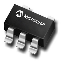
TC1016-3.3VLTTR Microchip Technology, TC1016-3.3VLTTR Datasheet - Page 11

TC1016-3.3VLTTR
Manufacturer Part Number
TC1016-3.3VLTTR
Description
IC REG LDO 3.3V 80MA SD SC70-5
Manufacturer
Microchip Technology
Specifications of TC1016-3.3VLTTR
Regulator Topology
Positive Fixed
Voltage - Output
3.3V
Voltage - Input
Up to 6V
Voltage - Dropout (typical)
0.15V @ 80mA
Number Of Regulators
1
Current - Output
80mA (Min)
Operating Temperature
-40°C ~ 125°C
Mounting Type
Surface Mount
Package / Case
SC-70-5, SC-88A, SOT-323-5, SOT-353, 5-TSSOP
Primary Input Voltage
6V
Output Voltage Fixed
3.3V
Dropout Voltage Vdo
150mV
No. Of Pins
5
Output Current
80mA
Operating Temperature Range
-40°C To +125°C
Peak Reflow Compatible (260 C)
Yes
Number Of Outputs
1
Polarity
Positive
Input Voltage Max
6 V
Output Voltage
3.3 V
Output Type
Fixed
Dropout Voltage (max)
0.2 V at 50 mA
Line Regulation
0.01 % / V
Load Regulation
0.23 %
Voltage Regulation Accuracy
0.5 %
Maximum Operating Temperature
+ 125 C
Mounting Style
SMD/SMT
Minimum Operating Temperature
- 40 C
Lead Free Status / RoHS Status
Lead free / RoHS Compliant
Current - Limit (min)
-
Lead Free Status / Rohs Status
Lead free / RoHS Compliant
Available stocks
Company
Part Number
Manufacturer
Quantity
Price
Company:
Part Number:
TC1016-3.3VLTTR
Manufacturer:
MICROCHIP
Quantity:
12 000
Part Number:
TC1016-3.3VLTTR
Manufacturer:
MICROCHIP/微芯
Quantity:
20 000
5.0
5.1
Integrated
regulator
approximately 160°C. The regulator remains off until
the die temperature drops to approximately 150°C.
5.2
The TC1016 is available in the SC-70 package. The
thermal resistance for the SC-70 package is approxi-
mately 450°C/W when the copper area used in the
PCB layout is similar to the JEDEC J51-7 high thermal
conductivity or Semi G42-88 standards. For applica-
tions with larger or thicker copper areas, the thermal
resistance can be lowered. See AN792 “A Method to
Determine How Much Power a SOT23 Can Dissipate in
an Application” (DS00792), for a method to determine
the thermal resistance for a particular application.
The TC1016 power dissipation capability is dependant
upon several variables: input voltage, output voltage,
load current, ambient temperature and maximum
junction temperature. The absolute maximum steady-
state junction temperature is rated at 125°C. The power
dissipation within the device is equal to:
EQUATION 5-1:
The V
pared to the (V
power dissipation within the LDO to be:
EQUATION 5-2:
To
capability, the following equation is used:
EQUATION 5-3:
© 2005 Microchip Technology Inc.
Where:
T
T
R
determine
A_MAX
J_MAX
IN
JA
P
x I
THERMAL CONSIDERATIONS
Thermal Shutdown
Power Dissipation
D
GND
P
= maximum junction temperature allowed
= the maximum ambient temperature allowed
= the thermal resistance from junction-to-air
off
=
thermal-protection
DMAX
P
D
term is typically very small when com-
V
IN
when
IN
=
the
-V
=
–
OUT
V
V
------------------------------------------------ -
IN
T
OUT
maximum
) x I
J_MAX
–
die
V
OUT
LOAD
R
I
–
LOAD
temperature
JA
T
A_MAX
circuitry
term simplifying the
I
power
LOAD
+
V
IN
shuts
I
dissipation
GND
exceeds
the
Given the following example:
Find:
1.
2.
3.
In this example, the TC1016 dissipates approximately
82.2 mW and the junction temperature is raised 37°C
over the 55°C ambient to 92°C. The absolute maximum
power dissipation is 155 mW when given a maximum
ambient temperature of 55°C.
Input voltage, output voltage or load current limits can
also be determined by substituting known values in
Equation 5-2 and Equation 5-3.
5.3
The primary path for heat conduction out of the SC-70
package is through the package leads. Using heavy,
wide traces at the pads of the device will facilitate the
removal of heat within the package, thus lowering the
thermal resistance R
resistance, the maximum internal power dissipation
capability of the package is increased.
FIGURE 5-1:
Internal power dissipation:
Junction temperature:
Maximum allowable dissipation:
V
V
I
T
LOAD
AMAX
IN
OUT
P
T
DMAX
J_MAX
Layout Considerations
C
= 3.0V to 4.1V
= 2.8V ±2.5%
= 60 mA (output current)
= 55°C (max. ambient temp.)
=
=
V
1
=
=
=
=
=
P
IN
D
37 C
82.2mW
82.2mWatts
92 C
P
V
4.1V 2.8
DMAX
=
IN_MAX
=
=
T
--------------------------------------------
125 C 55 C
---------------------------------- -
155mW
Suggested layout
+
J_MAX
–
JA
450 C/W
55 C
GND
. By lowering the thermal
R
SHDN
U1
–
R
V
–
–
JA
OUT_MIN
JA
T
0.975
450 C/W
A_MAX
TC1016
V
OUT
DS21666B-page 11
C
2
60mA
+
I
LOAD
T
AMAX


