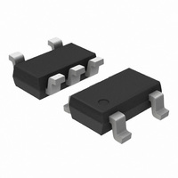
CAT823TTDI-GT3 ON Semiconductor, CAT823TTDI-GT3 Datasheet - Page 7

CAT823TTDI-GT3
Manufacturer Part Number
CAT823TTDI-GT3
Description
IC MPU SUPERVISOR CIRC SOT23-5
Manufacturer
ON Semiconductor
Type
Simple Reset/Power-On Resetr
Datasheet
1.CAT823TTDI-GT3.pdf
(15 pages)
Specifications of CAT823TTDI-GT3
Number Of Voltages Monitored
1
Output
Push-Pull, Totem Pole
Reset
Active Low
Reset Timeout
140 ms Minimum
Voltage - Threshold
3.08V
Operating Temperature
-40°C ~ 85°C
Mounting Type
Surface Mount
Package / Case
TSOT-23-5, TSOT-5, TSOP-5
Monitored Voltage
3 V or 3.3 V or 5 V
Undervoltage Threshold
3 V
Overvoltage Threshold
3.15 V
Manual Reset
Resettable
Watchdog
Yes
Supply Voltage (max)
5.5 V
Supply Voltage (min)
1.2 V
Supply Current (typ)
4 uA (Typ)
Maximum Power Dissipation
571 mW
Mounting Style
SMD/SMT
Maximum Operating Temperature
+ 85 C
Minimum Operating Temperature
- 40 C
Lead Free Status / RoHS Status
Lead free / RoHS Compliant
Other names
CAT823TTDI-G
CAT823TTDI-GT3TR
CAT823TTDI-GTR
CAT823TTDI-GTR
CAT823TTDI-GT3TR
CAT823TTDI-GTR
CAT823TTDI-GTR
Available stocks
Company
Part Number
Manufacturer
Quantity
Price
Company:
Part Number:
CAT823TTDI-GT3
Manufacturer:
ON Semiconductor
Quantity:
9 650
Part Number:
CAT823TTDI-GT3
Manufacturer:
ON/安森美
Quantity:
20 000
FUNCTIONAL DESCRIPTION
PROCESSOR RESET
The
conditions that are below the specified voltage trip
value (V
correct system operation. On power-up, RESET
RESET if available) are kept active for a minimum
delay t
above V
to stabilize. When V
value (V
RESET) are pulled active.
available) is specifically designed to provide the reset
input signals for processors. This provides reliable
and consistent operation as power is turned on, off or
during brownout conditions by maintaining the
processor operation in known conditions.
Figure 1. Pushbutton RESET
Figure 2. Timing Diagram – Pushbutton RESET
© 2010 SCILLC. All rights reserved.
Characteristics subject to change without notice
CAT823-825
RP
RST
RST
RST
of 140ms after the supply voltage (V
) and provide a reset output to maintain
), the reset output signals RESET
to allow the power supply and processor
RESET
RESET
MR
CC
detect
drops below the voltage trip
¯¯¯¯¯¯ (and RESET if
RESET
supply
V
IL
Voltage
Supply
t
PDLY
voltage
¯¯¯¯¯¯ (and
¯¯¯¯¯¯ (and
V
MR
CC
t
PB
CC
) rises
(V
CAT825
CC
)
7
MANUAL RESET
The CAT823 and CAT825 each have a Manual Reset
(MR
outputs. The MR
nection to a pushbutton (see Figure 1). The MR
is internally pulled up by 52kΩ resistor and must be
pulled low to cause the reset outputs to go active.
Internally, this input is debounced and timed such that
¯¯¯¯¯¯ (and RESET) signals of at least 140ms
RESET
minimum will be generated. The min 140ms t
commences as the Manual Reset input is released
from the low level. (see Figure 2)
¯¯¯ ) input to allow for alternative control of the reset
V
RESET
GND
RESET
IH
t
RP
V
V
¯¯¯ input is designed for direct con-
OH
OL
CAT823, CAT824, CAT825
Doc. No. MD-3027, Rev. D
¯¯¯ input
RP
delay


