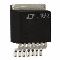
LT1210CR#PBF Linear Technology, LT1210CR#PBF Datasheet - Page 12

LT1210CR#PBF
Manufacturer Part Number
LT1210CR#PBF
Description
IC 35MHZ 1.1 AMP AMPLIFIER 7 DD
Manufacturer
Linear Technology
Type
Current Feedback Amplifierr
Datasheet
1.LT1210CT7PBF.pdf
(16 pages)
Specifications of LT1210CR#PBF
Amplifier Type
Current Feedback
Number Of Circuits
1
Slew Rate
90 V/µs
-3db Bandwidth
55MHz
Current - Input Bias
10µA
Voltage - Input Offset
3000µV
Current - Supply
35mA
Current - Output / Channel
2A
Voltage - Supply, Single/dual (±)
10 V ~ 30 V, ±5 V ~ 15 V
Operating Temperature
0°C ~ 70°C
Mounting Type
Surface Mount
Package / Case
TO-263-7, D²Pak (7 leads + Tab), TO-263CA
Rail/rail I/o Type
No
Number Of Elements
1
Common Mode Rejection Ratio
55dB
Input Offset Voltage
15mV
Single Supply Voltage (typ)
Not RequiredV
Dual Supply Voltage (typ)
±9/±12V
Voltage Gain In Db
71dB
Power Supply Rejection Ratio
60dB
Power Supply Requirement
Dual
Shut Down Feature
Yes
Single Supply Voltage (min)
Not RequiredV
Single Supply Voltage (max)
Not RequiredV
Dual Supply Voltage (min)
±5V
Dual Supply Voltage (max)
±15V
Technology
Bipolar
Operating Temp Range
0C to 70C
Operating Temperature Classification
Commercial
Mounting
Surface Mount
Pin Count
7 +Tab
Package Type
DDPAK
Lead Free Status / RoHS Status
Lead free / RoHS Compliant
Output Type
-
Gain Bandwidth Product
-
Lead Free Status / Rohs Status
Compliant
Available stocks
Company
Part Number
Manufacturer
Quantity
Price
LT1210
A
T7 Package, 7-Lead TO-220
Thermal Resistance (Junction-to-Case) = 5°C/W
Calculating Junction Temperature
The junction temperature can be calculated from the
equation:
where:
As an example, calculate the junction temperature for the
circuit in Figure 7 for the SO and R packages assuming a
70°C ambient temperature.
The device dissipation can be found by measuring the
supply currents, calculating the total dissipation and then
subtracting the dissipation in the load and feedback
network.
TYPICAL APPLICATIONS
12
V
IN
PPLICATI
OUTPUT OFFSET: < 500µV
SLEW RATE: 2V/µs
BANDWIDTH: 4MHz
STABLE WITH C
T
T
T
P
θ
P
J
J
A
JA
D
D
= (P
= Junction Temperature
= Ambient Temperature
= Device Dissipation
= (76mA)(10V) – (1.4V)
+
–
= Thermal Resistance (Junction-to-Ambient)
LT1097
D
)(θ
Precision × 10 High Current Amplifier
L
< 10nF
JA
O
) + T
U
A
S
500pF
I FOR ATIO
330Ω
U
2
/ 10 = 0.56W
1k
U
+
–
W
LT1210
SD
9.09k
COMP
3k
0.01µF
U
1210 TA03
OUT
then:
Since the maximum junction temperature is 150°C,
both packages are clearly acceptable.
T
T
J
J
= (0.56W)(46°C/W) + 70°C = 96°C
for the SO package with 1000 sq. mm topside
heat sinking
= (0.56W)(27°C/W) + 70°C = 85°C
for the R package with 1000 sq. mm topside heat
sinking
220Ω
CMOS Logic to Shutdown Interface
5V
10k
–
+
LT1210
–5V
5V
A
+
–
–15V
15V
LT1210
680Ω
76mA
SD
Figure 7
SD
2N3904
V
1210 TA04
O
10Ω
24k
V
O
= 1.4V
RMS
1210 F07
2V
0V
–2V
1210fa


