PA107DP Cirrus Logic Inc, PA107DP Datasheet - Page 6
PA107DP
Manufacturer Part Number
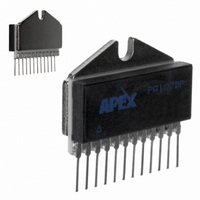
PA107DP
Description
HI PWR AMP MODULE 3KV/US SLEW
Manufacturer
Cirrus Logic Inc
Series
Apex Precision Power™r
Specifications of PA107DP
Amplifier Type
Power
Number Of Circuits
1
Slew Rate
3000 V/µs
Gain Bandwidth Product
180MHz
Current - Input Bias
300pA
Voltage - Input Offset
5000µV
Current - Supply
30mA
Current - Output / Channel
1.5A
Voltage - Supply, Single/dual (±)
±20 V ~ 100 V
Operating Temperature
-25°C ~ 85°C
Mounting Type
Through Hole
Package / Case
12-SIP
Input Voltage Range (max)
400 V
Input Voltage Range (min)
20 V
Input Offset Voltage
5 mV
Output Current (typ)
1.5 A
Supply Current
1.5 A
Maximum Power Dissipation
62.5 W
Maximum Operating Temperature
+ 85 C
Mounting Style
Through Hole
Minimum Operating Temperature
- 20 C
Lead Free Status / RoHS Status
Contains lead / RoHS non-compliant
Output Type
-
-3db Bandwidth
-
Lead Free Status / Rohs Status
No
Other names
598-1793
Available stocks
Company
Part Number
Manufacturer
Quantity
Price

Part Number:
PA107DP
Manufacturer:
APEX
Quantity:
20 000


PA107DP
5. REACTIVE LOADS
The PA107DP is stable at a gain of 20 or above when driving either inductive or capacitive loads. However an induc-
tor is essentially a short circuit at DC, therefore there must be enough resistance in series to keep low frequency
power within ratings.
When driving a 1nF capacitive load with a 180 V
with a 2.3 MHz sine wave, the power bandwidth frequency, results in 2.6 A
while driving a purely capacitive load is given by the formula:
Where:
Notice that the power increases as V
maximum. The power dissipated in the amplifier while driving 1 nF at 2.3 MHz would be 82.76 W. This would not
be a good thing to do! But driving 1 nF at 1 MHz at 180V
power rating.
This formula is optimistic; it is derived for an ideal class B amplifier output stage.
6. FEEDBACK CONSIDERATIONS
The output voltage of an unloaded PA107DP can easily go as high as 95 V. All of this voltage can be applied across
the feedback resistor, so the minimum value of a ½ W resistor in the feedback is 18050Ω. Practically, 20K is the
minimum value for a un-derated ½ W feedback resistor.
In order to provide the maximum slew rate, power bandwidth, and usable gain bandwidth; the PA107DP is not
designed to be unity gain stable. It is necessary to add external compensation for gains less than 20. Often lower
performance op-amps may be stabilized with a capacitor in parallel with the feedback resistor. This is because there
is effectively one additional pole affecting the response. In the case of the PA107DP, however there are multiple
poles clustered near 30 MHz, therefore this approach does not work. A method of compensation that works is to
choose a feedback capacitor such that the time constant of the feedback capacitor times the feedback resistor is
greater than 33 n-seconds. Also install a capacitor from pin 1 to ground, the summing junction, greater than 20
times as large as the feedback capacitor. The feedback capacitor or summing junction capacitor without the other
will degrade stability and often cause oscillation. With the compensation described the closed loop bandwidth will
be the reciprocal of 2�τ
Alternatively, at the expense of noise and offset, the amplifier can be stabilized by a resistor across the summing
junction such that the parallel combination of the input resistor and summing junction resistor is less than a twentieth
of the value of the feedback resistor. Note that this will increase noise and offset by to 20 times the RTI values, but
with 10 mV max offset and 13 nV/(Hz)
As seen by the very small values of capacitance used in compensation for low gain, stray feedback capacitance
and/or summing junction capacitance can have a VERY large effect on performance. Therefore stray capacitance
must be minimized in the layout. The summing junction lead must be as short as possible, and ground plane must
be kept away from the summing junction lead.
7. SLEW RATE AND FULL POWER BANDWIDTH
In the PA107DP the slew rate is measured from the 25% point to the 75% point of a 180V
is measured with no load and with auxiliary supplies at a nominal ±15 V and V
Power bandwidth is defined as the highest frequency at which an unloaded amplifier can have an undistorted sine
wave at full power as its output. This frequency can be calculated as the slew rate divided by � t imes the peak
to peak amplitude; which would be 4.7 MHz for the PA107DP. Unfortunately running full output at this frequency
causes internal dissipation of up to 107 W, well over the power limits for the PA107DP. Cutting the frequency to 2
MHz reduces internal dissipation to 34 W, acceptable with a good heatsink.
6
V
X
PK
V
S
C
= Peak Voltage
= Supply Voltage
= Capacitive Reactance
P = 2V
P = 2I
PK
PK
FB
V
V
.
S
S
/�
/�X
C
PK
1/2
increases, such that the maximum internal dissipation occurs when V
noise, performance will be acceptable for many applications.
P-P
square wave, the current peak is 1 A. Driving the same capacitor
P r o d u c t T e c h n o l o g y F r o m
P-P
would result in 36.0 W, which could be within the AC
P-P
. The power dissipated in the amplifier
S
supplies at a maximum ±100V.
P-P
square wave. Slew rate
PA107DPU
PK
is
Related parts for PA107DP
Image
Part Number
Description
Manufacturer
Datasheet
Request
R

Part Number:
Description:
OP AMP 90V 5A TO-3-8 CE
Manufacturer:
Cirrus Logic Inc
Datasheet:

Part Number:
Description:
Development Kit
Manufacturer:
Cirrus Logic Inc
Datasheet:
Part Number:
Description:
Development Kit
Manufacturer:
Cirrus Logic Inc
Datasheet:


Part Number:
Description:
High-efficiency PFC + Fluorescent Lamp Driver Reference Design
Manufacturer:
Cirrus Logic Inc
Datasheet:
Part Number:
Description:
Development Kit
Manufacturer:
Cirrus Logic Inc
Datasheet:
Part Number:
Description:
Development Kit
Manufacturer:
Cirrus Logic Inc
Datasheet:

Part Number:
Description:
Development Kit
Manufacturer:
Cirrus Logic Inc
Datasheet:
Part Number:
Description:
Development Kit
Manufacturer:
Cirrus Logic Inc
Datasheet:
Part Number:
Description:
Development Kit
Manufacturer:
Cirrus Logic Inc
Datasheet:

Part Number:
Description:
EVALUATION BOARD FOR CS8427
Manufacturer:
Cirrus Logic Inc
Datasheet:

Part Number:
Description:
BOARD EVAL FOR CS8416 RCVR
Manufacturer:
Cirrus Logic Inc
Datasheet:

Part Number:
Description:
EVALUATION BOARD FOR CS8420
Manufacturer:
Cirrus Logic Inc
Datasheet:

Part Number:
Description:
KIT DEVELOPMENT EP9315 ARM9
Manufacturer:
Cirrus Logic Inc
Datasheet:

Part Number:
Description:
KIT DEVELOPMENT EP9302 ARM9
Manufacturer:
Cirrus Logic Inc
Datasheet: