PA107DP Cirrus Logic Inc, PA107DP Datasheet - Page 5
PA107DP
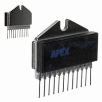
Manufacturer Part Number
PA107DP
Description
HI PWR AMP MODULE 3KV/US SLEW
Manufacturer
Cirrus Logic Inc
Series
Apex Precision Power™r
Specifications of PA107DP
Amplifier Type
Power
Number Of Circuits
1
Slew Rate
3000 V/µs
Gain Bandwidth Product
180MHz
Current - Input Bias
300pA
Voltage - Input Offset
5000µV
Current - Supply
30mA
Current - Output / Channel
1.5A
Voltage - Supply, Single/dual (±)
±20 V ~ 100 V
Operating Temperature
-25°C ~ 85°C
Mounting Type
Through Hole
Package / Case
12-SIP
Input Voltage Range (max)
400 V
Input Voltage Range (min)
20 V
Input Offset Voltage
5 mV
Output Current (typ)
1.5 A
Supply Current
1.5 A
Maximum Power Dissipation
62.5 W
Maximum Operating Temperature
+ 85 C
Mounting Style
Through Hole
Minimum Operating Temperature
- 20 C
Lead Free Status / RoHS Status
Contains lead / RoHS non-compliant
Output Type
-
-3db Bandwidth
-
Lead Free Status / Rohs Status
No
Other names
598-1793
Available stocks
Company
Part Number
Manufacturer
Quantity
Price

Part Number:
PA107DP
Manufacturer:
APEX
Quantity:
20 000


PIN DESCRIPTIONS
3. GENERAL
Please read Application Note 1 “General Operating Considerations” which covers stability, power supplies, heat
sinking, mounting, current limit, SOA interpretation, and specification interpretation. Visit www.cirrus.com for design
tools that help automate tasks such as calculations for stability, internal power dissipation, current limit, heat sink
selection, complete Application Notes library, Technical Seminar Workbook and Evaluation Kits.
CAUTION
In order to achieve the highest speed with limited space short circuit protection and thermal protection were sacri-
ficed. Do not short the output. Note that if current limiting at 1.5 A could be used, and the output was shorted, internal
dissipation would be 150 W. This would still destroy the amplifier, albeit more slowly.
4. INTERNAL POWER DISSIPATION AND HEATSINK SELECTION
With the unique combination of high voltage and speed of the PA107, traditional formulas for heatsink selection
will falsely lower the apparent power handling capability of this amplifier. To predict operating temperatures use the
following procedure:
Find internal dissipation (PD) resulting from driving the load. Refer to Apex Applications Note 1, General Operating
Considerations, paragraph 7. Find total quiescent power (PD
plus 0.021 times the total V
V
Calculate a heatsink rating which will maintain the case at 85°C or lower.
Where:
Calculate a heatsink rating which will maintain output transistor junctions at 150°C or lower.
Where:
Use the larger heatsink of these two calculations.
PA107DPU
SS
R
.
ØJC
T
T
T
C
Pin #
A
J
10
12
11
= maximum case temperature allowed
= maximum ambient temperature encountered
= maximum junction temperature allowed.
= AC or DC thermal resistance from the specification table.
1
2
3
4
5
6
7
8
9
R
R
ØSA
ØSA
=
=
P r o d u c t T e c h n o l o g y F r o m
PD + PD
T
Pin name
J
T
+V
GND
-V
OUT
+V
-V
- T
+V
C
-V
IN
AUX
AUX
- T
SP
SP
S
A
S
AUX
- (PD + PD
A
Q
PD + PD
(+V
-0.1°C/W
AUX
Summing Junction Input for Inverting Operational Amplifier
+10V to +18V Supply for Input Circuits
-10V to -18V Supply for Input Circuits
Ground
Open Pin
Open Pin
Open Pin
+20V to +100V Supply for Gain and Gate Driver Circuits
-20V to -100V Supply for Gain and Gate Driver Circuits
-20V to -100V Supply for Output Source Follower
High Power Output of Amplifier
+20V to +100V Supply for Output Source Follower
+ |-V
QOUT
Q
AUX
) • R
|). Find output stage quiescent power (PD
ØJC
-0.1°C/W
Q
) by multiplying 0.035 A by V
Description
QOUT
) by multiplying 0.001 by
SS
(total supply voltage),
PA107DP
5
Related parts for PA107DP
Image
Part Number
Description
Manufacturer
Datasheet
Request
R

Part Number:
Description:
OP AMP 90V 5A TO-3-8 CE
Manufacturer:
Cirrus Logic Inc
Datasheet:

Part Number:
Description:
Development Kit
Manufacturer:
Cirrus Logic Inc
Datasheet:
Part Number:
Description:
Development Kit
Manufacturer:
Cirrus Logic Inc
Datasheet:


Part Number:
Description:
High-efficiency PFC + Fluorescent Lamp Driver Reference Design
Manufacturer:
Cirrus Logic Inc
Datasheet:
Part Number:
Description:
Development Kit
Manufacturer:
Cirrus Logic Inc
Datasheet:
Part Number:
Description:
Development Kit
Manufacturer:
Cirrus Logic Inc
Datasheet:

Part Number:
Description:
Development Kit
Manufacturer:
Cirrus Logic Inc
Datasheet:
Part Number:
Description:
Development Kit
Manufacturer:
Cirrus Logic Inc
Datasheet:
Part Number:
Description:
Development Kit
Manufacturer:
Cirrus Logic Inc
Datasheet:

Part Number:
Description:
EVALUATION BOARD FOR CS8427
Manufacturer:
Cirrus Logic Inc
Datasheet:

Part Number:
Description:
BOARD EVAL FOR CS8416 RCVR
Manufacturer:
Cirrus Logic Inc
Datasheet:

Part Number:
Description:
EVALUATION BOARD FOR CS8420
Manufacturer:
Cirrus Logic Inc
Datasheet:

Part Number:
Description:
KIT DEVELOPMENT EP9315 ARM9
Manufacturer:
Cirrus Logic Inc
Datasheet:

Part Number:
Description:
KIT DEVELOPMENT EP9302 ARM9
Manufacturer:
Cirrus Logic Inc
Datasheet: