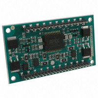
MP103FC Cirrus Logic Inc, MP103FC Datasheet - Page 4

MP103FC
Manufacturer Part Number
MP103FC
Description
HIGH POWER AMP MODULE 65V/USSLEW
Manufacturer
Cirrus Logic Inc
Series
Apex Precision Power™r
Specifications of MP103FC
Amplifier Type
Power
Number Of Circuits
2
Slew Rate
167 V/µs
-3db Bandwidth
230kHz
Current - Input Bias
3.3µA
Voltage - Input Offset
2000µV
Current - Supply
19mA
Current - Output / Channel
12A
Voltage - Supply, Single/dual (±)
30 V ~ 200 V, ±15 V ~ 100 V
Operating Temperature
0°C ~ 70°C
Mounting Type
Through Hole
Package / Case
42-DIP Module
Input Voltage Range (max)
200 V
Input Voltage Range (min)
20 V
Input Offset Voltage
2 mV
Output Current (typ)
15 A
Supply Current
1 mA
Maximum Power Dissipation
35 W
Maximum Operating Temperature
+ 70 C
Minimum Operating Temperature
0 C
Lead Free Status / RoHS Status
Contains lead / RoHS non-compliant
Output Type
-
Gain Bandwidth Product
-
Lead Free Status / Rohs Status
No
Other names
598-1794
MP103FC
Q4110212
MP103FC
Q4110212
Available stocks
Company
Part Number
Manufacturer
Quantity
Price
Company:
Part Number:
MP103FC
Manufacturer:
Cirrus
Quantity:
145
Part Number:
MP103FC
Manufacturer:
APEX
Quantity:
20 000
MP103
PIN DESCRIPTIONS
4
1,2,3
4,5,6
8
15
18,19,20
21,22,23
24,25,26
28
30
32
34
36
38
40,41,42
1.035
1.030
1.025
1.020
1.015
1.010
1.005
1.000
0.995
INPUT BIAS CURRENT vs. V
1.2
1.0
0.8
0.6
0.4
0.2
Pin #
110
100
0
OFFSET VOLTAGE vs. V
5
TOTAL SUPPLY VOLTAGE, V
5
0
TOTAL SUPPLY VOLTAGE, V
CASE TEMPERATURE, T
30
30
55
55
+V
I
Out_A
Out_B
+V
-V
I
IN_B
Feedback_B
GND
+V
Feedback_A
IN_A
-V
L
L
Pin name
_A
_B
25
80
S
S
AUX
S
S
80
_B
_A
_A
_B
105
105
130
130
50
155
155
S
SS
Positive high voltage power supply pins for channel A.
High current output pins for channel A. A current limit resistor must be placed between these pins
and the output pin 8.
Output pin for channel A.
Output pin for channel B.
Positive high voltage power supply pins for channel B.
Negative power supply pins for channel B.
High current output pins for channel B. A current limit resistor must be placed between these pins
and the output pin 15.
Input pin for channel B.
Feed back pin for channel B. This pin must be connected to output B pin 15 to close the feedback
loop. When connected directly to pin 15 the closed loop voltage gain of channel B is 65 V/V. The
gain can be increased by inserting a 1/4 W resistor between pins 30 and 15.
Ground
+24V voltage power supply pin. A 24 V power supply is required for operation of front end small
signal circuitry of each channel.
Feed back pin for channel A. This pin must be connected to output A pin 8 to close the feedback
loop. When connected directly to pin 8 the closed loop voltage gain of channel A is 65 V/V. The
gain can be increased by inserting a 1/4 W resistor between pins 36 and 8.
Input pin for channel A.
Negative power supply pins for channel A.
SUPPLY
180
C
SUPPLY
180
SS
(°C)
SS
(V)
(V)
205
205
75
105
100
EXTERNAL FEEDBACK RESISTOR, R
1.2
1.0
0.8
0.6
0.4
0.2
95
90
85
80
75
70
65
10
OFFSET VOLTAGE vs. V
100
0
0
5
TOTAL SUPPLY VOLTAGE, V
AMPLIFIER GAIN vs. R
OUTPUT VOLTAGE, V
120
10
500
P r o d u c t T e c h n o l o g y F r o m
140
15
1000
160
AUX
20
Description
O
(V)
SUPPLY
AUX
FDBK
FDBK
(V)
1500
180
25
(Ω)
INPUT BIAS CURRENT vs. V
0.9
0.8
0.7
0.6
1.4
1.2
1.0
0.8
0.6
0.4
0.2
450
400
350
300
250
200
150
SLEW RATE vs. TEMPERATURE
0
-40
-40
5
TOTAL SUPPLY VOLTAGE, V
CASE TEMPERATURE, T
CASE TEMPERATURE, TC (°C)
-20
-20
10
0
0
+SLR
-SLR
20
15
20
MP103U
40
40
20
AUX
C
60
AUX
60
(°C)
SUPPLY
(V)
80
25
80


