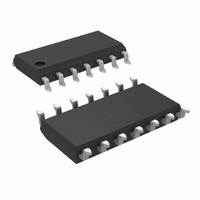
LF444CM/NOPB National Semiconductor, LF444CM/NOPB Datasheet - Page 2

LF444CM/NOPB
Manufacturer Part Number
LF444CM/NOPB
Description
IC OP AMP QUAD LOPWR JFET 14SOIC
Manufacturer
National Semiconductor
Series
BI-FET™r
Type
General Purpose Amplifierr
Specifications of LF444CM/NOPB
Amplifier Type
J-FET
Number Of Circuits
4
Slew Rate
1 V/µs
Gain Bandwidth Product
1MHz
Current - Input Bias
10pA
Voltage - Input Offset
3000µV
Current - Supply
600µA
Voltage - Supply, Single/dual (±)
10 V ~ 36 V, ±5 V ~ 18 V
Operating Temperature
0°C ~ 70°C
Mounting Type
Surface Mount
Package / Case
14-SOIC (3.9mm Width), 14-SOL
Bandwidth
1 MHz
Channel Separation
-120
Common Mode Rejection Ratio
95
Current, Input Bias
10 pA
Current, Input Offset
5 pA
Current, Output
8 mA
Current, Supply
0.6 mA
Impedance, Thermal
85 °C/W
Number Of Amplifiers
Quad
Package Type
SOIC-14
Power Dissipation
670 mW
Resistance, Input
10^12 Ohms
Temperature, Operating, Range
0 to +70 °C
Voltage, Gain
100 V/mV
Voltage, Input
6 to 44 V
Voltage, Noise
35 nV/sqrt Hz
Voltage, Offset
2 mV
Voltage, Output, High
13 V
Voltage, Output, Low
-13 V
Voltage, Supply
±15 V
Rail/rail I/o Type
No
Number Of Elements
4
Unity Gain Bandwidth Product
1MHz
Input Offset Voltage
10@±15VmV
Input Bias Current
100pA
Single Supply Voltage (typ)
Not RequiredV
Dual Supply Voltage (typ)
±5/±9/±12/±15V
Voltage Gain In Db
100dB
Power Supply Rejection Ratio
70dB
Power Supply Requirement
Dual
Shut Down Feature
No
Single Supply Voltage (min)
Not RequiredV
Single Supply Voltage (max)
Not RequiredV
Dual Supply Voltage (min)
±3V
Dual Supply Voltage (max)
±18V
Technology
BiFET
Operating Temp Range
0C to 70C
Operating Temperature Classification
Commercial
Mounting
Surface Mount
Pin Count
14
Lead Free Status / RoHS Status
Lead free / RoHS Compliant
Output Type
-
Current - Output / Channel
-
-3db Bandwidth
-
Lead Free Status / Rohs Status
RoHS Compliant part
Electrostatic Device
Other names
*LF444CM
*LF444CM/NOPB
LF444CM
*LF444CM/NOPB
LF444CM
www.national.com
V
∆V
I
I
R
A
V
V
CMRR
PSRR
I
OS
B
S
Symbol
OS
VOL
O
CM
IN
Absolute Maximum Ratings
If Military/Aerospace specified devices are required,
please contact the National Semiconductor Sales Office/
Distributors for availability and specifications.
DC Electrical Characteristics
Power Dissipation
T
θ
Supply Voltage
Differential Input Voltage
Input Voltage Range
Output Short Circuit
OS
jA
j
(Notes 3, 9)
(Note 1)
Duration (Note 2)
max
/∆T
(Typical)
Input Offset Voltage
Average TC of Input
Offset Voltage
Input Offset Current
Input Bias Current
Input Resistance
Large Signal Voltage
Gain
Output Voltage Swing
Input Common-Mode
Voltage Range
Common-Mode
Rejection Ratio
Supply Voltage
Rejection Ratio
Supply Current
Parameter
D Package
100˚C/W
900 mW
150˚C
Continuous
LF444A
±
±
±
R
0˚C ≤ T
−55˚C ≤ T
R
V
(Notes 5, 6)
V
(Notes 5, 6)
T
V
R
Over Temperature
V
R
(Note 7)
22V
38V
19V
S
S
j
S
S
S
S
L
S
= 25˚C
=
=
=
= 10 kΩ, T
=
= 10k, T
= 10 kΩ
≤ 10 kΩ
N, M Packages
±
±
±
±
15V
15V
15V, V
15V, R
A
670 mW
85˚C/W
115˚C
Continuous
≤ +70˚C
Conditions
(Note 11)
A
LF444
A
(Note 5)
≤ +125˚C
±
±
±
= 25˚C
18V
30V
15V
O
L
A
= 10 kΩ
=
= 25˚C
T
T
T
T
T
T
±
j
j
j
j
j
j
10V
= 25˚C
= 70˚C
= 125˚C
= 25˚C
= 70˚C
= 125˚C
2
See AN-450 “Surface Mounting Methods and Their Effect on
Product Reliability” for other methods of soldering surface
mount devices.
Operating Temperature Range
Storage Temperature Range
ESD Tolerance (Note 10)
Soldering Information
Dual-In-Line Packages
Small Outline Package
Min
±
±
(Soldering, 10 sec.)
Vapor Phase (60 sec.)
Infrared (15 sec.)
50
25
80
80
12
16
LF444A
10
Typ
±
100
+18
−17
100
100
0.6
10
10
2
5
13
12
Max
6.5
1.5
0.8
25
10
50
20
5
8
3
Min
±
±
25
15
70
70
12
11
LF444
−65˚C ≤ T
10
Typ
±
100
+14
−12
0.6
10
10
95
90
3
5
13
LF444A/LF444
12
be determined
Rating to
(Note 4)
260˚C
215˚C
220˚C
Max
100
1.5
1.0
10
12
50
A
3
≤ 150˚C
Units
µV/˚C
V/mV
V/mV
mV
mV
mV
mA
pA
nA
nA
pA
nA
nA
dB
dB
Ω
V
V
V


