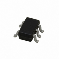
LMV721M7/NOPB National Semiconductor, LMV721M7/NOPB Datasheet - Page 11

LMV721M7/NOPB
Manufacturer Part Number
LMV721M7/NOPB
Description
IC OP AMP LOW VOLT LP SC-70-5
Manufacturer
National Semiconductor
Series
PowerWise®r
Datasheet
1.LMV721M7NOPB.pdf
(16 pages)
Specifications of LMV721M7/NOPB
Amplifier Type
General Purpose
Number Of Circuits
1
Output Type
Rail-to-Rail
Slew Rate
5.25 V/µs
Gain Bandwidth Product
10MHz
Current - Input Bias
260nA
Voltage - Input Offset
80µV
Current - Supply
1.03mA
Current - Output / Channel
52.6mA
Voltage - Supply, Single/dual (±)
2.2 V ~ 5.5 V, ±1.1 V ~ 2.25 V
Operating Temperature
-40°C ~ 85°C
Mounting Type
Surface Mount
Package / Case
SC-70-5, SC-88A, SOT-323-5, SOT-353, 5-TSSOP
Number Of Channels
1
Voltage Gain Db
94 dB
Common Mode Rejection Ratio (min)
70 dB
Input Offset Voltage
3 mV at 5 V
Operating Supply Voltage
3 V, 5 V
Supply Current
1.4 mA at 5 V
Maximum Operating Temperature
+ 85 C
Minimum Operating Temperature
- 40 C
Lead Free Status / RoHS Status
Lead free / RoHS Compliant
-3db Bandwidth
-
Lead Free Status / Rohs Status
Details
Other names
LMV721M7
LMV721M7TR
LMV721M7TR
Available stocks
Company
Part Number
Manufacturer
Quantity
Price
The output can swing to both rails, maximizing the signal-to-
noise ratio in a low voltage system.
4.4 Active Filter
4.4.1 Simple Low-Pass Active Filter
The simple low-pass filter is shown in Figure 9. Its low-pass
frequency gain (ω
frequency gains other than unity to be obtained. The filter has
a −20dB/decade roll-off after its corner frequency fc. R
should be chosen equal to the parallel combination of R
R
sponse of the filter is shown in Figure 10.
3
to minimize error due to bias current. The frequency re-
FIGURE 8. Single-Supply Inverting Amplifier
FIGURE 9. Simple Low-Pass Active Filter
→
o) is defined by −R
3
/R
1
. This allows low-
10092223
10092224
1
and
2
11
Note that the single-op-amp active filters are used in to the
applications that require low quality factor, Q(
quency (
product of gain times Q(
open loop voltage gain at the highest frequency of interest at
least 50 times larger than the gain of the filter at this frequen-
cy. In addition, the selected op amp should have a slew rate
that meets the following requirement:
Where ω
output peak-to-peak voltage.
FIGURE 11. A Battery Powered Microphone Preamplifier
Here is a LMV721 used as a microphone preamplifier. Since
the LMV721 is a low noise and low power op amp, it makes
it an ideal candidate as a battery powered microphone pream-
plifier. The LMV721 is connected in an inverting configuration.
Resistors, R
tween V
for single supply use. The gain of the preamplifier, which is
50 (34dB), is set by resistors R
gain bandwidth product for the LMV721 is 10 MHz. This is
sufficient for most audio application since the audio range is
typically from 20 Hz to 20kHz. A resistor R
bias the electret microphone. Capacitors C
placed at the input and output of the op amp to block out the
DC voltage offset.
FIGURE 10. Frequency Response of Simple Low-pass
Slew Rate
CC
≤
H
5KHz), and low gain (
is the highest frequency of interest, and V
= 3V and ground. Thus, this configures the op amp
1
= R
≥
Active Filter in Figure 9
0.5 x (ω
2
= 4.7kΩ, sets the reference half way be-
≤
H
100). The op amp should have an
V
OPP
3
≤
= 10kΩ and R
) X 10
10), or a small value for the
−6
V/µsec
5
= 5kΩ is used to
10092225
1
4
≤
= C
= 500kΩ. The
10), low fre-
www.national.com
2
OPP
= 4.7µF
10092244
is the


