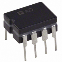
OP270EZ Analog Devices Inc, OP270EZ Datasheet - Page 3

OP270EZ
Manufacturer Part Number
OP270EZ
Description
IC OPAMP GP 5MHZ DUAL PREC 8CDIP
Manufacturer
Analog Devices Inc
Specifications of OP270EZ
Slew Rate
2.4 V/µs
Rohs Status
RoHS non-compliant
Amplifier Type
General Purpose
Number Of Circuits
2
Gain Bandwidth Product
5MHz
Current - Input Bias
5nA
Voltage - Input Offset
10µV
Current - Supply
4mA
Voltage - Supply, Single/dual (±)
±4.5 V ~ 18 V
Operating Temperature
-40°C ~ 85°C
Mounting Type
Through Hole
Package / Case
8-CDIP (0.300", 7.62mm)
Op Amp Type
Low Noise
No. Of Amplifiers
2
Bandwidth
5MHz
Supply Voltage Range
± 4.5V To ± 18V
Amplifier Case Style
DIP
No. Of Pins
8
Channel Separation
175
Common Mode Rejection Ratio
125
Current, Input Bias
5 nA
Current, Input Offset
1 nA
Current, Supply
4 mA
Impedance, Thermal
12 °C/W
Number Of Amplifiers
Dual
Package Type
CDIP-8
Resistance, Input
0.4 Megohms (Differential), 20 Gigaohms (Common-Mode)
Temperature, Operating, Range
-40 to +85 °C
Voltage, Gain
2300 V/mV
Voltage, Input
±12.5 V
Voltage, Noise
3.6 nV/sqrt Hz
Voltage, Offset
10 μV
Voltage, Output, High
+13.5 V
Voltage, Output, Low
-13.5 V
Voltage, Supply
±15 V
Output Type
-
Current - Output / Channel
-
-3db Bandwidth
-
Lead Free Status / RoHS Status
Contains lead / RoHS non-compliant
Available stocks
Company
Part Number
Manufacturer
Quantity
Price
Company:
Part Number:
OP270EZ
Manufacturer:
PMI
Quantity:
5 510
Company:
Part Number:
OP270EZ/FZ
Manufacturer:
PMI
Quantity:
5 510
Company:
Part Number:
OP270EZ/FZ
Manufacturer:
NAIS
Quantity:
5 510
SPECIFICATIONS
V
Table 1.
Parameter
Input Offset Voltage
Input Offset Current
Input Bias Current
Input Noise Voltage
Input Noise Voltage Density
Input Noise Current Density
Large-Signal Voltage Gain
Input Voltage Range
Output Voltage Swing
Common-Mode Rejection
Power Supply Rejection
Slew Rate
Supply Current
Gain Bandwidth Product
Channel Separation
Input Capacitance
Input Resistance
Settling Time
1
2
3
Guaranteed but not 100% tested.
Sample tested.
Guaranteed by CMR test.
S
Ratio
(All Amplifiers)
Differential Mode
Common Mode
= ±15 V, T
A
= 25°C, unless otherwise noted.
1
1
3
2
Symbol
V
I
I
e
e
e
e
i
i
i
A
IVR
V
CMR
PSRR
SR
I
GBP
CS
C
R
R
t
OS
B
n
n
n
SY
S
n
n
n
n
IN
INCM
OS
VO
O
IN
p-p
Test Conditions
V
V
0.1 Hz to 10 Hz
f
f
f
f
f
f
V
R
V
R
R
V
V
to ±18 V
No load
V
f
A
step to 0.01%
O
O
O
O
O
O
O
CM
CM
O
L
O
L
L
CM
S
O
V
= 10 Hz
= 100 Hz
= 1 kHz
= 10 Hz
= 100 Hz
= 1 kHz
= 10 Hz
= 10 kΩ
= 2 kΩ
≥ 2 kΩ
= ±4.5 V
= +1, 10 V,
= ±10 V,
= ±10 V,
= ±20 V p-p,
= 0 V
= 0 V
= ±11 V
Rev. E | Page 3 of 20
Min
1500
750
±12
±12
106
1.7
125
OP270E
Typ
10
1
5
80
3.6
3.2
3.2
1.1
0.7
0.6
2300
1200
±12.5
±13.5
125
0.56
2.4
4
5
175
3
0.4
20
5
Max
75
10
20
200
6.5
5.5
5.0
3.2
6.5
Min
1000
500
±12
±12
100
1.7
125
OP270F
Typ
20
3
10
80
3.6
3.2
3.2
1.1
0.7
0.6
1700
900
±12.5
±13.5
120
1.0
2.4
4
5
175
3
0.4
20
5
Max
150
15
40
200
6.5
5.5
5.0
5.6
6.5
Min
750
350
±12
±12
90
1.7
OP270G
Typ
50
5
15
80
3.6
3.2
3.2
1.1
0.7
0.6
1500
700
±12.5
±13.5
110
1.5
2.4
4
5
175
3
0.4
20
5
Max
250
20
60
5.6
6.5
OP270
Unit
μV
nA
nA
nV p-p
nV/√Hz
nV/√Hz
nV/√Hz
pA/√Hz
pA/√Hz
pA/√Hz
V/mV
V/mV
V
V
dB
μV/V
V/μs
mA
MHz
dB
pF
MΩ
GΩ
μs


