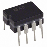
OP270EZ Analog Devices Inc, OP270EZ Datasheet - Page 13

OP270EZ
Manufacturer Part Number
OP270EZ
Description
IC OPAMP GP 5MHZ DUAL PREC 8CDIP
Manufacturer
Analog Devices Inc
Specifications of OP270EZ
Slew Rate
2.4 V/µs
Rohs Status
RoHS non-compliant
Amplifier Type
General Purpose
Number Of Circuits
2
Gain Bandwidth Product
5MHz
Current - Input Bias
5nA
Voltage - Input Offset
10µV
Current - Supply
4mA
Voltage - Supply, Single/dual (±)
±4.5 V ~ 18 V
Operating Temperature
-40°C ~ 85°C
Mounting Type
Through Hole
Package / Case
8-CDIP (0.300", 7.62mm)
Op Amp Type
Low Noise
No. Of Amplifiers
2
Bandwidth
5MHz
Supply Voltage Range
± 4.5V To ± 18V
Amplifier Case Style
DIP
No. Of Pins
8
Channel Separation
175
Common Mode Rejection Ratio
125
Current, Input Bias
5 nA
Current, Input Offset
1 nA
Current, Supply
4 mA
Impedance, Thermal
12 °C/W
Number Of Amplifiers
Dual
Package Type
CDIP-8
Resistance, Input
0.4 Megohms (Differential), 20 Gigaohms (Common-Mode)
Temperature, Operating, Range
-40 to +85 °C
Voltage, Gain
2300 V/mV
Voltage, Input
±12.5 V
Voltage, Noise
3.6 nV/sqrt Hz
Voltage, Offset
10 μV
Voltage, Output, High
+13.5 V
Voltage, Output, Low
-13.5 V
Voltage, Supply
±15 V
Output Type
-
Current - Output / Channel
-
-3db Bandwidth
-
Lead Free Status / RoHS Status
Contains lead / RoHS non-compliant
Available stocks
Company
Part Number
Manufacturer
Quantity
Price
Company:
Part Number:
OP270EZ
Manufacturer:
PMI
Quantity:
5 510
Company:
Part Number:
OP270EZ/FZ
Manufacturer:
PMI
Quantity:
5 510
Company:
Part Number:
OP270EZ/FZ
Manufacturer:
NAIS
Quantity:
5 510
For reference, typical source resistances of some signal sources are listed in Table 5.
Table 5. Typical Source Resistances
Device
Strain Gage
Magnetic Tapehead, Microphone
Magnetic Phonograph Cartridge
Linear Variable Differential Transformer
R1
5Ω
R2
5Ω
OP270
DUT
1.24kΩ
R3
200Ω
R4
OP27E
909Ω
R5
Figure 35. Peak-to-Peak Voltage Noise Test Circuit (0.1 Hz to 10 Hz)
<1500 Ω
Source Impedance
<500 Ω
<1500 Ω
<1500 Ω
2µF
C1
600Ω
R6
10kΩ
R8
D1, D2
1N4148
Rev. E | Page 13 of 20
OP27E
0.032µF
Comments
Typically used in low frequency applications.
Low I
direct coupling is used. OP270 I
Low I
applications. OP270 does not introduce any self-magnetization problems.
Used in rugged servo-feedback applications. The bandwidth of interest is
400 Hz to 5 kHz.
C2
306Ω
R9
B
B
is important to reduce self-magnetization problems in direct-coupled
is very important to reduce self-magnetization problems when
65.4kΩ
R10
65.4kΩ
0.22µF
R11
C3
0.22µF
C4
10kΩ
R12
B
can be disregarded.
OP42E
5.9kΩ
R13
4.99kΩ
R14
GAIN = 50,000
V
1µF
S
C5
= ±15V
e
OUT
OP270


