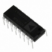
AD526JNZ Analog Devices Inc, AD526JNZ Datasheet - Page 10

AD526JNZ
Manufacturer Part Number
AD526JNZ
Description
IC AMP PGA 10MA 16DIP
Manufacturer
Analog Devices Inc
Type
Programmable Gain Amplifierr
Datasheet
1.AD526JNZ.pdf
(14 pages)
Specifications of AD526JNZ
Amplifier Type
Programmable Gain
Number Of Circuits
1
Slew Rate
24 V/µs
-3db Bandwidth
4MHz
Current - Input Bias
50pA
Voltage - Input Offset
400µV
Current - Supply
10mA
Current - Output / Channel
10mA
Voltage - Supply, Single/dual (±)
±4.5 V ~ 16.5 V
Operating Temperature
0°C ~ 70°C
Mounting Type
Through Hole
Package / Case
16-DIP (0.300", 7.62mm)
No. Of Amplifiers
1
Bandwidth
350kHz
No. Of Channels
1
Supply Voltage Range
± 4.5V To ± 16V
Amplifier Case Style
DIP
No. Of Pins
16
Operating Temperature Range
0°C To +70°C
Number Of Channels
1
Number Of Elements
1
Power Supply Requirement
Dual
Input Offset Voltage
1.5@±15VmV
Single Supply Voltage (typ)
Not RequiredV
Dual Supply Voltage (typ)
±5/±9/±12/±15V
Rail/rail I/o Type
No
Single Supply Voltage (min)
Not RequiredV
Single Supply Voltage (max)
Not RequiredV
Dual Supply Voltage (min)
±4.5V
Dual Supply Voltage (max)
±16.5V
Operating Temp Range
0C to 70C
Operating Temperature Classification
Commercial
Mounting
Through Hole
Pin Count
16
Package Type
PDIP
Lead Free Status / RoHS Status
Lead free / RoHS Compliant
Output Type
-
Gain Bandwidth Product
-
Lead Free Status / Rohs Status
Compliant
Available stocks
Company
Part Number
Manufacturer
Quantity
Price
GROUNDING AND BYPASSING
Proper signal and grounding techniques must be applied in
board layout so that specified performance levels of precision
data acquisition components, such as the AD526, are not
degraded.
As is shown in Figure 37, logic and signal grounds should be
separate. By connecting the signal source ground locally to the
AD526 analog ground Pins 5 and 6, gain accuracy of the
AD526 is maintained. This ground connection should not be
corrupted by currents associated with other elements within the
system.
AD526
V
IN
GROUND 1
ANALOG
AD526
Figure 37. Grounding and Bypassing
LATCHES AND LOGIC
GROUND 2
NETWORK
ANALOG
CLK
V
GAIN
A2
A1
A0
IN
A1
16
1
+15V
+V
AD526
16
LOGIC AND LATCHES
S
A0
0.1 F
15
AMP
2
GAIN NETWORK
8
14
CS CLK
3
0.1 F
GROUND
4
DIGITAL
FORCE
SENSE
13
4
–15V
V
V
–V
2
OUT
OUT
S
0.1 F
0.1 F
12
A2
5
1
+5V
11
B
6
+
–
–V
+V
10
7
Figure 38. Cascaded Operation
S
S
CONVERTER
0.1 F
AD574
12-BIT
9
8
0.1 F
A/D
1 F
OUT
FORCE
OUT
SENSE
+5V
–10–
Utilizing the force and sense outputs of the AD526, as shown in
Figure 38, avoids signal drops along etch runs to low impedance
loads.
16
A1
1
AD526
16
LOGIC AND LATCHES
A0
15
2
GAIN NETWORK
8
14
CS CLK
3
4
V
128
16
32
64
OUT
13
Table II. Logic Table for Figure 38
4
1
2
4
8
2
/V
A2
12
5
1
IN
+5V
11
B
6
+
–
A2
0
0
0
0
1
1
1
1
–V
+V
10
7
S
S
9
8
0.1 F
0.1 F
OUT
FORCE
OUT
SENSE
A1
0
0
1
1
0
0
1
1
V
A0
0
1
0
1
0
1
0
1
OUT
REV. D


