MC68HC705SR3CP Freescale Semiconductor, MC68HC705SR3CP Datasheet - Page 67
MC68HC705SR3CP
Manufacturer Part Number
MC68HC705SR3CP
Description
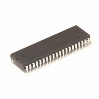
IC MCU 3.75K 2.1MHZ OTP 40-DIP
Manufacturer
Freescale Semiconductor
Series
HC05r
Specifications of MC68HC705SR3CP
Core Processor
HC05
Core Size
8-Bit
Speed
4MHz
Peripherals
LED, POR
Number Of I /o
32
Program Memory Size
3.75KB (3.75K x 8)
Program Memory Type
OTP
Ram Size
192 x 8
Voltage - Supply (vcc/vdd)
3 V ~ 5.5 V
Data Converters
A/D 4x8b
Oscillator Type
Internal
Operating Temperature
-40°C ~ 85°C
Package / Case
40-DIP (0.600", 15.24mm)
Lead Free Status / RoHS Status
Contains lead / RoHS non-compliant
Eeprom Size
-
Connectivity
-
Available stocks
Company
Part Number
Manufacturer
Quantity
Price
Company:

Part Number:
MC68HC705SR3CP
Manufacturer:
MOTOROLA
Quantity:
82
Part Number:
MC68HC705SR3CP
Manufacturer:
MOTCROLA
Quantity:
20 000
Part Number:
MC68HC705SR3CPE
Manufacturer:
FREESCALE
Quantity:
20 000


8.3.8
The relative addressing mode is only used in branch instructions. In relative addressing, the
contents of the 8-bit signed byte (the offset) following the opcode are added to the PC if, and only
if, the branch conditions are true. Otherwise, control proceeds to the next instruction. The span of
relative addressing is from –126 to +129 from the opcode address. The programmer need not
calculate the offset when using the Freescale assembler, since it calculates the proper offset and
checks to see that it is within the span of the branch.
8.3.9
In the bit set/clear addressing mode, the bit to be set or cleared is part of the opcode. The byte
following the opcode specifies the address of the byte in which the specified bit is to be set or
cleared. Any read/write bit in the first 256 locations of memory, including I/O, can be selectively set
or cleared with a single two-byte instruction.
8.3.10
The bit test and branch addressing mode is a combination of direct addressing and relative
addressing. The bit to be tested and its condition (set or clear) is included in the opcode. The
address of the byte to be tested is in the single byte immediately following the opcode byte (EA1).
The signed relative 8-bit offset in the third byte (EA2) is added to the PC if the specified bit is set
or cleared in the specified memory location. This single three-byte instruction allows the program
to branch based on the condition of any readable bit in the first 256 locations of memory. The span
of branch is from –125 to +130 from the opcode address. The state of the tested bit is also
transferred to the carry bit of the condition code register.
MC68HC05SR3
Relative
Bit set/clear
Bit test and branch
Address bus high ← 0; Address bus low ← (PC+1)
Address bus high ← 0; Address bus low ← (PC+1)
EA2 = PC+3+(PC+2); PC ← EA2 if branch taken;
EA = PC+2+(PC+1); PC ← EA if branch taken;
CPU CORE AND INSTRUCTION SET
otherwise EA = PC ← PC+2
EA1 = (PC+1); PC ← PC+2
EA = (PC+1); PC ← PC+2
otherwise PC ← PC+3
Freescale
TPG
8-13
8
Related parts for MC68HC705SR3CP
Image
Part Number
Description
Manufacturer
Datasheet
Request
R

Part Number:
Description:
Manufacturer:
Freescale Semiconductor, Inc
Datasheet:
Part Number:
Description:
Manufacturer:
Freescale Semiconductor, Inc
Datasheet:
Part Number:
Description:
Manufacturer:
Freescale Semiconductor, Inc
Datasheet:
Part Number:
Description:
Manufacturer:
Freescale Semiconductor, Inc
Datasheet:
Part Number:
Description:
Manufacturer:
Freescale Semiconductor, Inc
Datasheet:
Part Number:
Description:
Manufacturer:
Freescale Semiconductor, Inc
Datasheet:
Part Number:
Description:
Manufacturer:
Freescale Semiconductor, Inc
Datasheet:
Part Number:
Description:
Manufacturer:
Freescale Semiconductor, Inc
Datasheet:
Part Number:
Description:
Manufacturer:
Freescale Semiconductor, Inc
Datasheet:
Part Number:
Description:
Manufacturer:
Freescale Semiconductor, Inc
Datasheet:
Part Number:
Description:
Manufacturer:
Freescale Semiconductor, Inc
Datasheet:
Part Number:
Description:
Manufacturer:
Freescale Semiconductor, Inc
Datasheet:
Part Number:
Description:
Manufacturer:
Freescale Semiconductor, Inc
Datasheet:
Part Number:
Description:
Manufacturer:
Freescale Semiconductor, Inc
Datasheet:
Part Number:
Description:
Manufacturer:
Freescale Semiconductor, Inc
Datasheet: