MC68HC705SR3CP Freescale Semiconductor, MC68HC705SR3CP Datasheet - Page 53
MC68HC705SR3CP
Manufacturer Part Number
MC68HC705SR3CP
Description
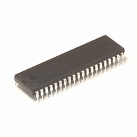
IC MCU 3.75K 2.1MHZ OTP 40-DIP
Manufacturer
Freescale Semiconductor
Series
HC05r
Specifications of MC68HC705SR3CP
Core Processor
HC05
Core Size
8-Bit
Speed
4MHz
Peripherals
LED, POR
Number Of I /o
32
Program Memory Size
3.75KB (3.75K x 8)
Program Memory Type
OTP
Ram Size
192 x 8
Voltage - Supply (vcc/vdd)
3 V ~ 5.5 V
Data Converters
A/D 4x8b
Oscillator Type
Internal
Operating Temperature
-40°C ~ 85°C
Package / Case
40-DIP (0.600", 15.24mm)
Lead Free Status / RoHS Status
Contains lead / RoHS non-compliant
Eeprom Size
-
Connectivity
-
Available stocks
Company
Part Number
Manufacturer
Quantity
Price
Company:

Part Number:
MC68HC705SR3CP
Manufacturer:
MOTOROLA
Quantity:
82
Part Number:
MC68HC705SR3CP
Manufacturer:
MOTCROLA
Quantity:
20 000
Part Number:
MC68HC705SR3CPE
Manufacturer:
FREESCALE
Quantity:
20 000


7.2
The ADSCR is a read/write register containing status and control bits for the ADC.
COCO — COnversion COmplete
This read-only status bit is set when a conversion is completed, indicating that the ADC Data
Register contains a valid result. This COCO bit is cleared either by a write to the ADSCR or a read
of the ADC Data Register. Once the COCO bit is cleared, a new conversion automatically starts.
If the COCO bit is not cleared, conversions are initiated every 32 cycles. In this continuous
conversion mode the ADC Data Register is refreshed with new data, every 32 cycles, and the
COCO bit remains set.
ADRC — ADC RC Oscillator Control
The RC oscillator option must be used if the internal processor is running below 1MHz. A
stabilization time of typically 1ms is required when switching to the RC oscillator option.
ADON — ADC On
When the ADC is turned from OFF to ON, it requires a time t
stabilize. During this time ADC conversion results may be inaccurate. Switching the ADC off
disables the internal charge pump and RC oscillator (if selected by ADRC=1), and hence saving
power.
CH2:CH0 — Channel Select Bits
These three bits selects one of eight ADC channels for the conversion. Channels 0 to 3
correspond to inputs AN0-AN3 on port pins PD0-PD3 respectively. Channels 4 and 5 are the ADC
reference inputs V
for internal reference points. Table 7-1 shows the signals selected by the channel select bits.
MC68HC05SR3
1 (set)
0 (clear) –
1 (set)
0 (clear) –
1 (set)
0 (clear) –
Address
$0E
ADC Status and Control Register (ADSCR)
COCO
–
–
–
bit 7
RH
and V
An ADC conversion has completed; ADC Data Register ($0F)
contains valid conversion result.
ADC conversion not completed.
ADC uses RC oscillator as clock source.
ADC uses internal processor clock as clock source.
ADC is switched ON.
ADC is switched OFF.
ADRC
bit 6
RL
ANALOG TO DIGITAL CONVERTER
, on port pins PD4 and PD5 respectively. Channels 6 and 7 are used
ADON
bit 5
bit 4
bit 3
bit 2
CH2
ADON
bit 1
CH1
for the current sources to
bit 0
CH0
000- -000
on reset
State
Freescale
TPG
7-3
7
Related parts for MC68HC705SR3CP
Image
Part Number
Description
Manufacturer
Datasheet
Request
R

Part Number:
Description:
Manufacturer:
Freescale Semiconductor, Inc
Datasheet:
Part Number:
Description:
Manufacturer:
Freescale Semiconductor, Inc
Datasheet:
Part Number:
Description:
Manufacturer:
Freescale Semiconductor, Inc
Datasheet:
Part Number:
Description:
Manufacturer:
Freescale Semiconductor, Inc
Datasheet:
Part Number:
Description:
Manufacturer:
Freescale Semiconductor, Inc
Datasheet:
Part Number:
Description:
Manufacturer:
Freescale Semiconductor, Inc
Datasheet:
Part Number:
Description:
Manufacturer:
Freescale Semiconductor, Inc
Datasheet:
Part Number:
Description:
Manufacturer:
Freescale Semiconductor, Inc
Datasheet:
Part Number:
Description:
Manufacturer:
Freescale Semiconductor, Inc
Datasheet:
Part Number:
Description:
Manufacturer:
Freescale Semiconductor, Inc
Datasheet:
Part Number:
Description:
Manufacturer:
Freescale Semiconductor, Inc
Datasheet:
Part Number:
Description:
Manufacturer:
Freescale Semiconductor, Inc
Datasheet:
Part Number:
Description:
Manufacturer:
Freescale Semiconductor, Inc
Datasheet:
Part Number:
Description:
Manufacturer:
Freescale Semiconductor, Inc
Datasheet:
Part Number:
Description:
Manufacturer:
Freescale Semiconductor, Inc
Datasheet: