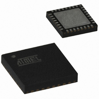
AT89C5131A-PUTIM Atmel, AT89C5131A-PUTIM Datasheet - Page 151

AT89C5131A-PUTIM
Manufacturer Part Number
AT89C5131A-PUTIM
Description
IC 8051 MCU FLASH 32K USB 32QFN
Manufacturer
Atmel
Series
AT89C513xr
Datasheet
1.AT89C5130A-PUTUM.pdf
(188 pages)
Specifications of AT89C5131A-PUTIM
Core Processor
C52X2
Core Size
8-Bit
Speed
48MHz
Connectivity
I²C, SPI, UART/USART, USB
Peripherals
LED, POR, PWM, WDT
Number Of I /o
18
Program Memory Size
32KB (32K x 8)
Program Memory Type
FLASH
Eeprom Size
4K x 8
Ram Size
1.25K x 8
Voltage - Supply (vcc/vdd)
2.7 V ~ 5.5 V
Oscillator Type
Internal
Operating Temperature
-40°C ~ 85°C
Package / Case
32-VQFN Exposed Pad, 32-HVQFN, 32-SQFN, 32-DHVQFN
For Use With
AT89STK-10 - KIT EVAL APPL MASS STORAGEAT89STK-05 - KIT STARTER FOR AT89C5131
Lead Free Status / RoHS Status
Contains lead / RoHS non-compliant
Data Converters
-
- Current page: 151 of 188
- Download datasheet (2Mb)
22. Reset
22.1
22.2
22.3
4337K–USB–04/08
Introduction
Reset Input
Reset Output
The reset sources are: Power Management, Hardware Watchdog, PCA Watchdog and Reset
input.
Figure 22-1. Reset schematic
The Reset input can be used to force a reset pulse longer than the internal reset controlled by
the Power Monitor. RST input has a pull-up resistor allowing power-on reset by simply connect-
ing an external capacitor to V
characteristics are discussed in the Section “DC Characteristics” of the AT89C5130A/31A-M
datasheet.
Figure 22-2. Reset Circuitry and Power-On Reset
As detailed in Section “Hardware Watchdog Timer”, page 158, the WDT generates a 96-clock
period pulse on the RST pin. In order to properly propagate this pulse to the rest of the applica-
tion in case of external capacitor or power-supply supervisor circuit, a 1 kΩ resistor must be
added as shown Figure 22-3.
RST
RST
Watchdog
Watchdog
Hardware
Monitor
Power
PCA
a. RST input circuitry
VCC
S S
as shown in Figure 22-2. Resistor value and input
To internal reset
AT89C5130A/31A-M
b. Power-on Reset
Internal Reset
VSS
+
RST
151
Related parts for AT89C5131A-PUTIM
Image
Part Number
Description
Manufacturer
Datasheet
Request
R

Part Number:
Description:
Manufacturer:
Atmel Corporation
Datasheet:

Part Number:
Description:
Manufacturer:
Atmel Corporation
Datasheet:

Part Number:
Description:
IC 8051 MCU FLASH 32K USB 32QFN
Manufacturer:
Atmel
Datasheet:

Part Number:
Description:
IC 8051 MCU FLASH 32K USB 52PLCC
Manufacturer:
Atmel
Datasheet:

Part Number:
Description:
IC MCU 32KB 3-3.6V USB 48-VQFN
Manufacturer:
Atmel
Datasheet:

Part Number:
Description:
MCU 8051 32K FLASH USB 28-SOIC
Manufacturer:
Atmel
Datasheet:

Part Number:
Description:
IC 8051 MCU FLASH 32K USB 64VQFP
Manufacturer:
Atmel
Datasheet:

Part Number:
Description:
MCU 8051 32K FLASH USB 64-VQFP
Manufacturer:
Atmel
Datasheet:

Part Number:
Description:
MCU 8051 32K FLASH USB 28-SOIC
Manufacturer:
Atmel
Datasheet:

Part Number:
Description:
MCU 8051 32K FLASH USB 52-PLCC
Manufacturer:
Atmel
Datasheet:

Part Number:
Description:
IC 8051 MCU FLASH 32K USB 48QFN
Manufacturer:
Atmel
Datasheet:

Part Number:
Description:
IC 8051 MCU FLASH 32K USB 64VQFP
Manufacturer:
Atmel
Datasheet:

Part Number:
Description:
IC 8051 MCU FLASH 32K USB 52PLCC
Manufacturer:
Atmel
Datasheet:

Part Number:
Description:
IC 8051 MCU FLASH 32K USB 28SOIC
Manufacturer:
Atmel
Datasheet:


