M38227ECFP Renesas Electronics America, M38227ECFP Datasheet - Page 51
M38227ECFP
Manufacturer Part Number
M38227ECFP
Description
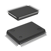
IC 740 MCU EPROM 48K 80QFP
Manufacturer
Renesas Electronics America
Series
740/38000r
Datasheet
1.M38227ECFP.pdf
(82 pages)
Specifications of M38227ECFP
Core Processor
740
Core Size
8-Bit
Speed
8MHz
Connectivity
SIO, UART/USART
Peripherals
LCD
Number Of I /o
49
Program Memory Size
48KB (48K x 8)
Program Memory Type
OTP
Ram Size
1K x 8
Voltage - Supply (vcc/vdd)
2.5 V ~ 5.5 V
Data Converters
A/D 8x8b
Oscillator Type
Internal
Operating Temperature
-20°C ~ 85°C
Package / Case
80-QFP
Lead Free Status / RoHS Status
Contains lead / RoHS non-compliant
Eeprom Size
-
Available stocks
Company
Part Number
Manufacturer
Quantity
Price
Company:

Part Number:
M38227ECFP
Manufacturer:
Renesas Electronics America
Quantity:
10 000
Part Number:
M38227ECFP
Manufacturer:
MIT
Quantity:
20 000
Company:
Part Number:
M38227ECFP#U0
Manufacturer:
Renesas Electronics America
Quantity:
10 000
Part Number:
M38227ECFP#U0
Manufacturer:
RENESAS/瑞萨
Quantity:
20 000


(3) Oscillator concerns
In order to obtain the stabilized operation clock on the user system
and its condition, contact the oscillator manufacturer and select
the oscillator and oscillation circuit constants. Be careful espe-
cially when range of votage and temperature is wide.
Also, take care to prevent an oscillator that generates clocks for a
microcomputer operation from being affected by other signals.
Fig. 49 Wiring for a large current signal line/Wiring of signal
48
Keeping oscillator away from large current signal lines
Install a microcomputer (and especially an oscillator) as far as
possible from signal lines where a current larger than the toler-
ance of current value flows.
Reason
In the system using a microcomputer, there are signal lines for
controlling motors, LEDs, and thermal heads or others. When a
large current flows through those signal lines, strong noise oc-
curs because of mutual inductance.
Installing oscillator away from signal lines where potential levels
change frequently
Install an oscillator and a connecting pattern of an oscillator
away from signal lines where potential levels change frequently.
Also, do not cross such signal lines over the clock lines or the
signal lines which are sensitive to noise.
Reason
Signal lines where potential levels change frequently (such as
the CNTR pin signal line) may affect other lines at signal rising
edge or falling edge. If such lines cross over a clock line, clock
waveforms may be deformed, which causes a microcomputer
failure or a program runaway.
Keeping oscillator away from large current signal lines
levels change frequently
Installing oscillator away from signal lines where potential
Mutual inductance
lines where potential levels change frequently
Do not cross
current
Large
M
N.G.
GND
CNTR
X
X
V
Microcomputer
X
X
V
SS
IN
OUT
IN
OUT
SS
(4) Analog input
The analog input pin is connected to the capacitor of a voltage
comparator. Accordingly, sufficient accuracy may not be obtained
by the charge/discharge current at the time of A-D conversion
when the analog signal source of high-impedance is connected to
an analog input pin. In order to obtain the A-D conversion result
stabilized more, please lower the impedance of an analog signal
source, or add the smoothing capacitor to an analog input pin.
(5) Difference of memory type and size
When Mask ROM and PROM version and memory size differ in
one group, actual values such as an electrical characteristics, A-D
conversion accuracy, and the amount of -proof of noise incorrect
operation may differ from the ideal values.
When these products are used switching, perform system evalua-
tion for each product of every after confirming product
specification.
(6) Wiring to V
Connect an approximately 5 k
shortest possible in series and also to the V
Note: Even when a circuit which included an approximately 5 k
resistor is used in the Mask ROM version, the microcomputer
operates correctly.
The V
input pin for the built-in PROM. When programming in the built-in
PROM, the impedance of the V
current for writing flow into the built-in PROM. Because of this,
noise can enter easily. If noise enters the V
struction codes or data are read from the built-in PROM, which
may cause a program runaway.
Fig. 50 Wiring for the V
Electric Characteristic Differences Between
Mask ROM and One Time PROM Version MCUs
There are differences in electric characteristics, operation margin,
noise immunity, and noise radiation between Mask ROM and
One Time PROM version MCUs due to the difference in the manufac-
turing processes.
When manufacturing an application system with the One TIme PROM
version and then switching to use of the Mask ROM version,
please perform sufficient evaluations for the commercial
samples of the Mask ROM version.
Reason
PP
pin of the One Time PROM version is the power source
SINGLE-CHIP 8-BIT CMOS MICROCOMPUTER
PP
pin of One Time PROM version
P4
MITSUBISHI MICROCOMPUTERS
0
PP
/V
V
SS
PP
pin of One Time PROM
PP
resistor to the V
pin is low to allow the electric
About 5k
3822 Group
PP
SS
pin, abnormal in-
pin.
PP
pin the
Related parts for M38227ECFP
Image
Part Number
Description
Manufacturer
Datasheet
Request
R

Part Number:
Description:
KIT STARTER FOR M16C/29
Manufacturer:
Renesas Electronics America
Datasheet:

Part Number:
Description:
KIT STARTER FOR R8C/2D
Manufacturer:
Renesas Electronics America
Datasheet:

Part Number:
Description:
R0K33062P STARTER KIT
Manufacturer:
Renesas Electronics America
Datasheet:

Part Number:
Description:
KIT STARTER FOR R8C/23 E8A
Manufacturer:
Renesas Electronics America
Datasheet:

Part Number:
Description:
KIT STARTER FOR R8C/25
Manufacturer:
Renesas Electronics America
Datasheet:

Part Number:
Description:
KIT STARTER H8S2456 SHARPE DSPLY
Manufacturer:
Renesas Electronics America
Datasheet:

Part Number:
Description:
KIT STARTER FOR R8C38C
Manufacturer:
Renesas Electronics America
Datasheet:

Part Number:
Description:
KIT STARTER FOR R8C35C
Manufacturer:
Renesas Electronics America
Datasheet:

Part Number:
Description:
KIT STARTER FOR R8CL3AC+LCD APPS
Manufacturer:
Renesas Electronics America
Datasheet:
Part Number:
Description:
KIT STARTER FOR RX610
Manufacturer:
Renesas Electronics America
Datasheet:

Part Number:
Description:
KIT STARTER FOR R32C/118
Manufacturer:
Renesas Electronics America
Datasheet:

Part Number:
Description:
KIT DEV RSK-R8C/26-29
Manufacturer:
Renesas Electronics America
Datasheet:

Part Number:
Description:
KIT STARTER FOR SH7124
Manufacturer:
Renesas Electronics America
Datasheet:

Part Number:
Description:
KIT STARTER FOR H8SX/1622
Manufacturer:
Renesas Electronics America
Datasheet:

Part Number:
Description:
KIT DEV FOR SH7203
Manufacturer:
Renesas Electronics America
Datasheet: