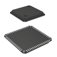
DF2211CUNP24V Renesas Electronics America, DF2211CUNP24V Datasheet - Page 35

DF2211CUNP24V
Manufacturer Part Number
DF2211CUNP24V
Description
MCU 16BIT FLASH 3V 64K 64-QFN
Manufacturer
Renesas Electronics America
Series
H8® H8S/2200r
Datasheet
1.DF2218UTF24V.pdf
(758 pages)
Specifications of DF2211CUNP24V
Core Processor
H8S/2000
Core Size
16-Bit
Speed
24MHz
Connectivity
SCI, SmartCard, USB
Peripherals
DMA, POR, PWM, WDT
Number Of I /o
37
Program Memory Size
64KB (64K x 8)
Program Memory Type
FLASH
Ram Size
8K x 8
Voltage - Supply (vcc/vdd)
2.7 V ~ 3.6 V
Data Converters
A/D 6x10b
Oscillator Type
External
Operating Temperature
-20°C ~ 75°C
Package / Case
64-QFN
Lead Free Status / RoHS Status
Lead free / RoHS Compliant
Eeprom Size
-
Available stocks
Company
Part Number
Manufacturer
Quantity
Price
Company:
Part Number:
DF2211CUNP24V
Manufacturer:
Renesas Electronics America
Quantity:
135
- Current page: 35 of 758
- Download datasheet (5Mb)
17.9 Program/Erase Protection.................................................................................................. 583
17.10 Interrupt Handling when Programming/Erasing Flash Memory....................................... 584
17.11 Programmer Mode ............................................................................................................ 585
17.12 Power-Down States for Flash Memory............................................................................. 586
17.13 Flash Memory Programming and Erasing Precautions ..................................................... 587
17.14 Note on Switching from F-ZTAT Version to Masked ROM Version .............................. 592
Section 18 Masked ROM
18.1 Features ............................................................................................................................. 593
Section 19 Clock Pulse Generator
19.1 Register Descriptions ........................................................................................................ 596
19.2 System Clock Oscillator.................................................................................................... 600
19.3 Duty Adjustment Circuit ................................................................................................... 602
19.4 Medium-Speed Clock Divider .......................................................................................... 602
19.5 Bus Master Clock Selection Circuit .................................................................................. 602
19.6 Subclock Oscillator ........................................................................................................... 603
19.7 Subclock Waveform Generation Circuit ........................................................................... 604
19.8 PLL Circuit for USB ......................................................................................................... 604
19.9 Usage Notes ...................................................................................................................... 605
Section 20 Power-Down Modes
20.1 Register Descriptions ........................................................................................................ 611
20.2 Medium-Speed Mode........................................................................................................ 617
17.8.2 Erase/Erase-Verify............................................................................................... 581
17.9.1 Hardware Protection ............................................................................................ 583
17.9.2 Software Protection.............................................................................................. 583
17.9.3 Error Protection.................................................................................................... 583
19.1.1 System Clock Control Register (SCKCR) ........................................................... 596
19.1.2 Low Power Control Register (LPWRCR)............................................................ 597
19.2.1 Connecting a Crystal Resonator........................................................................... 600
19.2.2 Inputting External Clock...................................................................................... 601
19.6.1 Connecting 32.768-kHz Crystal Resonator.......................................................... 603
19.6.2 Handling Pins when Subclock Not Required....................................................... 603
19.9.1 Note on Crystal Resonator ................................................................................... 605
19.9.2 Note on Board Design.......................................................................................... 605
19.9.3 Note on Switchover of External Clock ................................................................ 605
20.1.1 Standby Control Register (SBYCR) .................................................................... 611
20.1.2 Timer Control/Status Register (TCSR_1) ............................................................ 613
20.1.3 Module Stop Control Registers A to C (MSTPCRA to MSTPCRC)................... 614
20.1.4 Extended Module Stop Register (EXMDLSTP).................................................. 617
.................................................................................................. 593
...................................................................................... 607
.................................................................................. 595
Rev.7.00 Dec. 24, 2008 Page xxxiii of liv
REJ09B0074-0700
Related parts for DF2211CUNP24V
Image
Part Number
Description
Manufacturer
Datasheet
Request
R

Part Number:
Description:
KIT STARTER FOR M16C/29
Manufacturer:
Renesas Electronics America
Datasheet:

Part Number:
Description:
KIT STARTER FOR R8C/2D
Manufacturer:
Renesas Electronics America
Datasheet:

Part Number:
Description:
R0K33062P STARTER KIT
Manufacturer:
Renesas Electronics America
Datasheet:

Part Number:
Description:
KIT STARTER FOR R8C/23 E8A
Manufacturer:
Renesas Electronics America
Datasheet:

Part Number:
Description:
KIT STARTER FOR R8C/25
Manufacturer:
Renesas Electronics America
Datasheet:

Part Number:
Description:
KIT STARTER H8S2456 SHARPE DSPLY
Manufacturer:
Renesas Electronics America
Datasheet:

Part Number:
Description:
KIT STARTER FOR R8C38C
Manufacturer:
Renesas Electronics America
Datasheet:

Part Number:
Description:
KIT STARTER FOR R8C35C
Manufacturer:
Renesas Electronics America
Datasheet:

Part Number:
Description:
KIT STARTER FOR R8CL3AC+LCD APPS
Manufacturer:
Renesas Electronics America
Datasheet:

Part Number:
Description:
KIT STARTER FOR RX610
Manufacturer:
Renesas Electronics America
Datasheet:

Part Number:
Description:
KIT STARTER FOR R32C/118
Manufacturer:
Renesas Electronics America
Datasheet:

Part Number:
Description:
KIT DEV RSK-R8C/26-29
Manufacturer:
Renesas Electronics America
Datasheet:

Part Number:
Description:
KIT STARTER FOR SH7124
Manufacturer:
Renesas Electronics America
Datasheet:

Part Number:
Description:
KIT STARTER FOR H8SX/1622
Manufacturer:
Renesas Electronics America
Datasheet:

Part Number:
Description:
KIT DEV FOR SH7203
Manufacturer:
Renesas Electronics America
Datasheet:


