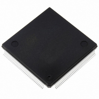
ST10F276Z5Q3 STMicroelectronics, ST10F276Z5Q3 Datasheet - Page 201

ST10F276Z5Q3
Manufacturer Part Number
ST10F276Z5Q3
Description
MCU 16BIT 832KB FLASH 144-PQFP
Manufacturer
STMicroelectronics
Series
ST10r
Datasheet
1.ST10F276Z5T3.pdf
(239 pages)
Specifications of ST10F276Z5Q3
Core Processor
ST10
Core Size
16-Bit
Speed
64MHz
Connectivity
ASC, CAN, EBI/EMI, I²C, SSC, UART/USART
Peripherals
POR, PWM, WDT
Number Of I /o
111
Program Memory Size
832KB (832K x 8)
Program Memory Type
FLASH
Ram Size
68K x 8
Voltage - Supply (vcc/vdd)
4.5 V ~ 5.5 V
Data Converters
A/D 24x10b
Oscillator Type
Internal
Operating Temperature
-40°C ~ 125°C
Package / Case
144-QFP
Processor Series
ST10F27x
Core
ST10
Data Bus Width
16 bit
Data Ram Size
68 KB
Interface Type
CAN/I2C
Maximum Clock Frequency
64 MHz
Number Of Programmable I/os
111
Number Of Timers
5
Operating Supply Voltage
4.5 V to 5.5 V
Maximum Operating Temperature
+ 125 C
Mounting Style
SMD/SMT
Minimum Operating Temperature
- 40 C
On-chip Adc
24-ch x 10-bit
For Use With
497-6399 - KIT DEV STARTER ST10F276Z5
Lead Free Status / RoHS Status
Lead free / RoHS Compliant
Eeprom Size
-
Lead Free Status / Rohs Status
Lead free / RoHS Compliant
Other names
497-5580
Available stocks
Company
Part Number
Manufacturer
Quantity
Price
Company:
Part Number:
ST10F276Z5Q3
Manufacturer:
AD
Quantity:
230
Company:
Part Number:
ST10F276Z5Q3
Manufacturer:
STMicroelectronics
Quantity:
10 000
Company:
Part Number:
ST10F276Z5Q3TR
Manufacturer:
STMicroelectronics
Quantity:
10 000
- Current page: 201 of 239
- Download datasheet (3Mb)
ST10F276Z5
23.8.9
23.8.10
23.8.11
Example 2
●
●
●
●
●
●
PLL Jitter
Two kinds of PLL jitter are defined:
●
●
Jitter at the PLL output is caused by:
●
●
Jitter in the input clock
PLL acts like a low pass filter for any jitter in the input clock. Input Clock jitter with the
frequencies within the PLL loop bandwidth is passed to the PLL output and higher frequency
jitter (frequency > PLL bandwidth) is attenuated at 20dB/decade.
Noise in the PLL loop
This condition again is attributed to the following sources:
●
●
Device noise of the circuit in the PLL
Long term jitter is inversely proportional to the bandwidth of the PLL: The wider the loop
bandwidth, the lower the jitter due to noise in the loop. Moreover, long term jitter is
practically independent of the multiplication factor.
The most noise sensitive circuit in the PLL circuit is definitely the VCO (Voltage Controlled
Oscillator). There are two main sources of noise: Thermal (random noise, frequency
independent thus practically white noise) and flicker (low frequency noise, 1/f). For the
frequency characteristics of the VCO circuitry, the effect of the thermal noise results in a 1/f
region in the output noise spectrum, while the flicker noise in a 1/f
PLL input and supposing that the VCO is dominated by its 1/f
accumulated jitter is proportional to the square root of N, where N is the number of clock
F
P0(15:13) = ‘100’ (multiplication by 5)
PLL input frequency = 2 MHz
VCO frequency = 80 MHz
PLL output frequency = 40 MHz (VCO frequency divided by 2)
F
Self referred single period jitter
Also called "Period Jitter", it can be defined as the difference of the T
where T
minimum time period of the PLL output clock.
Self referred long term jitter
Also called "N period jitter", it can be defined as the difference of T
T
minimum time difference between N + 1 clock rising edges. Here N should be kept
sufficiently large to have the long term jitter. For N = 1, this becomes the single period
jitter.
Jitter in the input clock
Noise in the PLL loop
Device noise of the circuit in the PLL
Noise in supply and substrate
XTAL
CPU
max
is the maximum time difference between N + 1 clock rising edges and T
= 40 MHz (no effect of output prescaler)
= 8 MHz
max
is the maximum time period of the PLL output clock and T
2
noise, the R.M.S. value of the
Electrical characteristics
3
. Assuming a noiseless
max
max
min
and T
and T
is the
min
min
min
, where
201/239
is the
,
2
Related parts for ST10F276Z5Q3
Image
Part Number
Description
Manufacturer
Datasheet
Request
R

Part Number:
Description:
MCU 16BIT 832K FLASH 144-LQFP
Manufacturer:
STMicroelectronics
Datasheet:

Part Number:
Description:
MCU 16BIT 832K FLASH 144-LQFP
Manufacturer:
STMicroelectronics
Datasheet:

Part Number:
Description:
MCU 16BIT 832K FLASH 144-PQFP
Manufacturer:
STMicroelectronics
Datasheet:

Part Number:
Description:
MCU 16BIT 832K FLASH 144-PQFP
Manufacturer:
STMicroelectronics
Datasheet:

Part Number:
Description:
16-bit Microcontrollers - MCU 16-Bit MCU 832 kByte 68 KB RAM CMOS
Manufacturer:
STMicroelectronics

Part Number:
Description:
STMicroelectronics [RIPPLE-CARRY BINARY COUNTER/DIVIDERS]
Manufacturer:
STMicroelectronics
Datasheet:

Part Number:
Description:
STMicroelectronics [LIQUID-CRYSTAL DISPLAY DRIVERS]
Manufacturer:
STMicroelectronics
Datasheet:

Part Number:
Description:
BOARD EVAL FOR MEMS SENSORS
Manufacturer:
STMicroelectronics
Datasheet:

Part Number:
Description:
NPN TRANSISTOR POWER MODULE
Manufacturer:
STMicroelectronics
Datasheet:

Part Number:
Description:
TURBOSWITCH ULTRA-FAST HIGH VOLTAGE DIODE
Manufacturer:
STMicroelectronics
Datasheet:

Part Number:
Description:
Manufacturer:
STMicroelectronics
Datasheet:

Part Number:
Description:
DIODE / SCR MODULE
Manufacturer:
STMicroelectronics
Datasheet:


