STM32F102RBT6 STMicroelectronics, STM32F102RBT6 Datasheet - Page 14
STM32F102RBT6
Manufacturer Part Number
STM32F102RBT6
Description
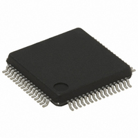
MCU ARM 32BIT 128KB FLASH 64LQFP
Manufacturer
STMicroelectronics
Series
STM32r
Datasheet
1.STEVAL-MKI109V1.pdf
(69 pages)
Specifications of STM32F102RBT6
Core Processor
ARM® Cortex-M3™
Core Size
32-Bit
Speed
48MHz
Connectivity
I²C, IrDA, LIN, SPI, UART/USART, USB
Peripherals
DMA, PDR, POR, PVD, PWM, Temp Sensor, WDT
Number Of I /o
51
Program Memory Size
128KB (128K x 8)
Program Memory Type
FLASH
Ram Size
16K x 8
Voltage - Supply (vcc/vdd)
2 V ~ 3.6 V
Data Converters
A/D 16x12b
Oscillator Type
Internal
Operating Temperature
-40°C ~ 85°C
Package / Case
64-LQFP
For Use With
497-10030 - STARTER KIT FOR STM32497-8853 - BOARD DEMO STM32 UNIV USB-UUSCIKSDKSTM32-PL - KIT IAR KICKSTART STM32 CORTEXM3497-8512 - KIT STARTER FOR STM32F10XE MCU497-8505 - KIT STARTER FOR STM32F10XE MCU497-8304 - KIT STM32 MOTOR DRIVER BLDC497-6438 - BOARD EVALUTION FOR STM32 512K497-6289 - KIT PERFORMANCE STICK FOR STM32MCBSTM32UME - BOARD EVAL MCBSTM32 + ULINK-MEMCBSTM32U - BOARD EVAL MCBSTM32 + ULINK2497-6053 - KIT STARTER FOR STM32497-6052 - KIT STARTER FOR STM32497-6050 - KIT STARTER FOR STM32497-6049 - KIT EVALUATION LOW COST STM32497-6048 - BOARD EVALUATION FOR STM32497-6047 - KIT DEVELOPMENT FOR STM32497-5046 - KIT TOOL FOR ST7/UPSD/STR7 MCU
Lead Free Status / RoHS Status
Lead free / RoHS Compliant
Eeprom Size
-
Lead Free Status / Rohs Status
Details
Other names
497-8312
Available stocks
Company
Part Number
Manufacturer
Quantity
Price
Company:

Part Number:
STM32F102RBT6
Manufacturer:
STMicroelectronics
Quantity:
10 000


Description
14/69
Boot modes
At startup, boot pins are used to select one of five boot options:
●
●
●
The boot loader is located in System Memory. It is used to reprogram the Flash memory by
using USART1. For further details please refer to AN2606.
Power supply schemes
●
●
●
For more details on how to connect power pins, refer to
Power supply supervisor
The device has an integrated power on reset (POR)/power down reset (PDR) circuitry. It is
always active, and ensures proper operation starting from/down to 2 V. The device remains
in reset mode when V
external reset circuit.
The device features an embedded programmable voltage detector (PVD) that monitors the
V
generated when V
than the V
message and/or put the MCU into a safe state. The PVD is enabled by software.
Refer to
V
Voltage regulator
The regulator has three operation modes: main (MR), low power (LPR) and power down.
●
●
●
This regulator is always enabled after reset. It is disabled in Standby mode, providing high
impedance output.
DD
POR/PDR
/V
Boot from User Flash
Boot from System Memory
Boot from embedded SRAM
V
Provided externally through V
V
and PLL (minimum voltage to be applied to V
V
V
registers (through power switch) when V
MR is used in the nominal regulation mode (Run)
LPR is used in the Stop mode
Power down is used in Standby mode: the regulator output is in high impedance: the
kernel circuitry is powered down, inducing zero consumption (but the contents of the
registers and SRAM are lost)
DD
SSA
DDA
BAT
DDA
Table 10: Embedded reset and power control block characteristics
= 2.0 to 3.6 V: External power supply for I/Os and the internal regulator.
, V
= 1.8 to 3.6 V: Power supply for RTC, external clock 32 kHz oscillator and backup
PVD
and V
power supply and compares it to the V
and V
DDA
threshold. The interrupt service routine can then generate a warning
PVD
SSA
= 2.0 to 3.6 V: External analog power supplies for ADC, Reset blocks, RCs
DD
.
must be connected to V
/V
DD
DDA
is below a specified threshold, V
drops below the V
Doc ID 15056 Rev 3
DD
pins.
DD
DD
PVD
and V
is not present.
PVD
threshold and/or when V
DDA
SS
threshold. An interrupt can be
is 2.4 V when the ADC is used).
Figure 8: Power supply
, respectively.
POR/PDR
STM32F102x8, STM32F102xB
, without the need for an
DD
for the values of
/V
DDA
scheme.
is higher
Related parts for STM32F102RBT6
Image
Part Number
Description
Manufacturer
Datasheet
Request
R

Part Number:
Description:
DEV KIT FOR STM32
Manufacturer:
STMicroelectronics
Datasheet:

Part Number:
Description:
MCU ARM 128KB FLASH MEM 64-LQFP
Manufacturer:
STMicroelectronics
Datasheet:

Part Number:
Description:
MCU ARM 32BIT 128KB FLASH 64BGA
Manufacturer:
STMicroelectronics
Datasheet:

Part Number:
Description:
MCU ARM 32BIT 256K FLASH 144LQFP
Manufacturer:
STMicroelectronics
Datasheet:

Part Number:
Description:
KIT STARTER FOR STM32F10X
Manufacturer:
STMicroelectronics
Datasheet:

Part Number:
Description:
MCU ARM 128K FLASH/TIMER
Manufacturer:
STMicroelectronics
Datasheet:

Part Number:
Description:
MCU ARM 128KB FLASH MEM 100-LQFP
Manufacturer:
STMicroelectronics
Datasheet:

Part Number:
Description:
MCU 32BIT ARM 64K FLASH 36VFQFPN
Manufacturer:
STMicroelectronics
Datasheet:
Part Number:
Description:
MCU ARM 32BIT 32KB FLASH 48LQFP
Manufacturer:
STMicroelectronics
Datasheet:
Part Number:
Description:
MCU ARM 32BIT 64KB FLASH 64LQFP
Manufacturer:
STMicroelectronics
Datasheet:
Part Number:
Description:
MCU ARM 32BIT 384KB FLASH 64LQFP
Manufacturer:
STMicroelectronics
Datasheet:

Part Number:
Description:
MCU 32BIT ARM 512K FLASH 100-LQF
Manufacturer:
STMicroelectronics
Datasheet:
Part Number:
Description:
MCU ARM 32BIT 512KB FLASH 144BGA
Manufacturer:
STMicroelectronics
Datasheet:
Part Number:
Description:
MCU ARM 32BIT 512K FLASH 144LQFP
Manufacturer:
STMicroelectronics
Datasheet:
Part Number:
Description:
MCU 32BIT ARM 16K FLASH 64LQFP
Manufacturer:
STMicroelectronics
Datasheet: