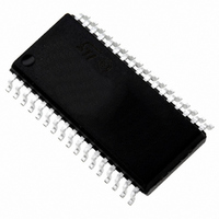
ST72F621L4M1 STMicroelectronics, ST72F621L4M1 Datasheet - Page 103

ST72F621L4M1
Manufacturer Part Number
ST72F621L4M1
Description
IC MCU 8BIT LS 16K 34-SOIC
Manufacturer
STMicroelectronics
Series
ST7r
Datasheet
1.ST72F622L2M1.pdf
(139 pages)
Specifications of ST72F621L4M1
Core Processor
ST7
Core Size
8-Bit
Speed
8MHz
Connectivity
SCI, SPI, USB
Peripherals
DMA, LVD, POR, PWM, WDT
Number Of I /o
23
Program Memory Size
16KB (16K x 8)
Program Memory Type
FLASH
Ram Size
768 x 8
Voltage - Supply (vcc/vdd)
4 V ~ 5.5 V
Data Converters
A/D 8x10b
Oscillator Type
Internal
Operating Temperature
0°C ~ 70°C
Package / Case
34-SOIC (7.5mm Width)
Processor Series
ST72F6x
Core
ST7
Data Bus Width
8 bit
Data Ram Size
768 B
Interface Type
SCI, SPI, USB
Maximum Clock Frequency
12 MHz
Number Of Programmable I/os
23
Number Of Timers
2
Operating Supply Voltage
4 V to 5.5 V
Maximum Operating Temperature
+ 70 C
Mounting Style
SMD/SMT
Minimum Operating Temperature
0 C
On-chip Adc
10 bit
For Use With
497-5046 - KIT TOOL FOR ST7/UPSD/STR7 MCU
Lead Free Status / RoHS Status
Lead free / RoHS Compliant
Eeprom Size
-
Lead Free Status / Rohs Status
In Transition
Other names
497-2112-5
Available stocks
Company
Part Number
Manufacturer
Quantity
Price
Company:
Part Number:
ST72F621L4M1
Manufacturer:
ST
Quantity:
2 272
Company:
Part Number:
ST72F621L4M1
Manufacturer:
ST
Quantity:
5
12.2.3 Thermal Characteristics
Notes:
1. The maximum chip-junction temperature is based on technology characteristics.
12.3 OPERATING CONDITIONS
12.3.1 General Operating Conditions (standard voltage ROM and Flash devices)
.
Figure 55. f
12.3.2 Operating Conditions with Low Voltage Detector (LVD)
Subject to general operating conditions for V
Notes:
1. Not tested, guaranteed by design.
2. Not tested in production, guaranteed by characterization.
3. The V
V
V
V
Vt
Symbol
IT+
IT-
hyst
Symbol
POR
V
V
f
V
CPU
T
DDA
SSA
DD
A
f
CPU
DD
Symbol
T
8
4
2
0
[MHz]
STG
rise time rate condition is needed to insure a correct device power-on and LVD reset. Not tested in production.
T
Low Voltage Reset Threshold (V
Low Voltage Reset Threshold (V
J
2.5
Hysteresis (V
V
CPU
DD
Operating Supply Voltage
Analog reference voltage
Analog reference voltage
Operating frequency
Ambient temperature range
rise time rate
Versus V
NOT GUARANTEED
3.0
Storage temperature range
Maximum junction temperature
FUNCTIONALITY
IT+
Parameter
IN THIS AREA
Parameter
DD
- V
3)
for standard voltage devices
IT-
)
3.5
DD
DD
4
falling)
rising)
Ratings
DD
, f
Doc ID 6996 Rev 5
CPU
f
V
V
1)
CPU
f
f
4.5
OSC
OSC
DD
DD
, and T
Conditions
= 8 MHz
Max. Variation 50V/ms
Max. Variation 50V/ms
= 12MHz
= 6MHz
Conditions
A
5
. Refer to
5.5
V
Min
V
Figure 15 on page
4
0
DD
SS
SUPPLY VOLTAGE [V]
120
-65 to +150
3.45
Min
3.6
0.5
Value
Typ
FUNCTIONALITY
GUARANTEED
IN THIS AREA
(UNLESS OTHERWISE
SPECIFIED IN THE
TABLES OF
PARAMETRIC DATA)
175
2)
5
Typ
150
3.65
3.8
1)
2)
Max
V
V
5.5
70
8
4
DD
SS
21.
180
Max
3.95
3.8
50
2)
Unit
Unit
MHz
103/139
°C
°C
°C
V/ms
Unit
mV
V
V


