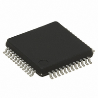
ST72F63BH6T1 STMicroelectronics, ST72F63BH6T1 Datasheet - Page 162

ST72F63BH6T1
Manufacturer Part Number
ST72F63BH6T1
Description
IC MCU 8BIT 32K FLASH 48-LQFP
Manufacturer
STMicroelectronics
Series
ST7r
Datasheet
1.ST72F63BD6U1TR.pdf
(186 pages)
Specifications of ST72F63BH6T1
Core Processor
ST7
Core Size
8-Bit
Speed
8MHz
Connectivity
I²C, SCI, USB
Peripherals
DMA, LVD, POR, PWM, WDT
Number Of I /o
27
Program Memory Size
32KB (32K x 8)
Program Memory Type
FLASH
Ram Size
1K x 8
Voltage - Supply (vcc/vdd)
4 V ~ 5.5 V
Data Converters
A/D 12x8b
Oscillator Type
External
Operating Temperature
0°C ~ 70°C
Package / Case
48-LQFP
Processor Series
ST72F6x
Core
ST7
Data Bus Width
8 bit
Data Ram Size
1 KB
Interface Type
I2C, SCI
Maximum Clock Frequency
8 MHz
Number Of Programmable I/os
27
Number Of Timers
1
Maximum Operating Temperature
+ 70 C
Mounting Style
SMD/SMT
Development Tools By Supplier
ST7MDTU3-EPB/US, ST72F63B-SK/RAIS, ST7MDTU3-EMU3, STX-RLINK
Minimum Operating Temperature
0 C
On-chip Adc
8 bit, 8 Channel / 8 bit, 12 Channel
For Use With
497-5521 - EVAL BOARD LOW SPEED USB
Lead Free Status / RoHS Status
Lead free / RoHS Compliant
Eeprom Size
-
Lead Free Status / Rohs Status
Details
Available stocks
Company
Part Number
Manufacturer
Quantity
Price
Company:
Part Number:
ST72F63BH6T1
Manufacturer:
TI
Quantity:
10
Company:
Part Number:
ST72F63BH6T1
Manufacturer:
STMicroelectronics
Quantity:
10 000
Electrical characteristics
Table 77.
1. Legend: R
2. The above variations depend on the accuracy of the external components used.
3. For speeds around 200 kHz, achieved speed can have ±5% tolerance.
4. For other speed ranges, achieved speed can have ±2% tolerance.
13.11
162/186
400
300
200
100
50
20
(kHz)
f
SCL
NA
NA
83h
10h
24h
5Fh
R
P
P
Table 77
SCL line frequency.
SCL frequency
8-bit ADC
Subject to general operating conditions for V
Table 78.
1. Unless otherwise specified, typical data are based on T
2. When V
3. Any added external serial resistor will downgrade the ADC accuracy (especially for resistance greater than
4. The stabilization time of the AD converter is masked by the first t
= External pull-up resistance; f
=3.3 kΩ R
Symbol
C
t
R
f
V
t
STAB
ADC
ADC
10k
is then always valid.
ADC
V
AIN
AIN
DD
Ω
). Data based on characterization results, not tested in production.
= 4.1 V
gives the values to be written in the I2CCCR register to obtain the required I
NA
NA
83h
10h
24h
5Fh
ADC clock frequency
Conversion range voltage
External input resistor
Internal sample and hold
capacitor
Stabilization time after ADC
enable
Conversion time (Sample+Hold)
- Sample capacitor loading time
- Hold conversion time
DDA
P
=4.7 kΩ R
8-bit ADC characteristics
and V
f
(1)(2)(3)(4)
CPU
SSA
=4 MHz
Parameter
pins are not available on the pinout, the ADC refer to V
NA
NA
83h
10h
24h
5Fh
P
=3.3 kΩ R
SCL
= I
V
DD
2
C speed; NA = not achievable.
Doc ID 7516 Rev 8
= 5 V
(2)
NA
NA
83h
10h
24h
5Fh
P
=4.7 kΩ R
I2CCCR Value
f
f
CPU
ADC
Conditions
DD
=8 MHz,
=2 MHz
83h
85h
24h
4Ch
FFh
8Ah
P
, f
A
=3.3 kΩ R
=25°C and V
OSC
V
DD
, and T
LOAD
= 4.1 V
83
85h
89h
23h
4Ch
FFh
. The first conversion after the enable
P
DD
A
=4.7 kΩ R
V
Min
-V
SSA
unless otherwise specified.
-
-
-
f
SS
CPU
=5V.
DD
=8 MHz
Typ
and V
83h
85h
8Ah
24h
4Ch
FFh
0
6
-
-
-
6
4
8
(4)
P
(1)
=3.3 kΩ R
SS.
V
V
DD
10
Max
DDA
4
-
(3)
= 5 V
ST7263Bxx
83h
85h
8Ah
23h
4Ch
FFh
P
=4.7 kΩ
1/f
2
MHz
Unit
κΩ
pF
C
µs
V
ADC


