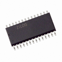
Z86E3116SSG Zilog, Z86E3116SSG Datasheet - Page 39

Z86E3116SSG
Manufacturer Part Number
Z86E3116SSG
Description
IC MICROCONTROLLER 2K 28-SOIC
Manufacturer
Zilog
Series
Z8®r
Datasheet
1.Z86E4001ZDV.pdf
(64 pages)
Specifications of Z86E3116SSG
Core Processor
Z8
Core Size
8-Bit
Speed
16MHz
Peripherals
POR, WDT
Number Of I /o
24
Program Memory Size
2KB (2K x 8)
Program Memory Type
OTP
Ram Size
125 x 8
Voltage - Supply (vcc/vdd)
3.5 V ~ 5.5 V
Oscillator Type
Internal
Operating Temperature
0°C ~ 70°C
Package / Case
28-SOIC (7.5mm Width)
Processor Series
Z86E3xx
Core
Z8
Data Bus Width
8 bit
Data Ram Size
125 B
Maximum Clock Frequency
8 MHz
Number Of Programmable I/os
24
Number Of Timers
2
Operating Supply Voltage
3.5 V to 5.5 V
Maximum Operating Temperature
+ 70 C
Mounting Style
SMD/SMT
Minimum Operating Temperature
0 C
Lead Free Status / RoHS Status
Lead free / RoHS Compliant
Eeprom Size
-
Data Converters
-
Connectivity
-
Lead Free Status / Rohs Status
Details
Other names
269-3968
Z86E3116SSG
Z86E3116SSG
Zilog
When more than one interrupt is pending, priorities are re-
solved by a programmable priority encoder that is con-
trolled by the Interrupt Priority Register (IPR). An interrupt
machine cycle is activated when an interrupt request is
granted. Thus, disabling all subsequent interrupts, saves
the Program Counter and Status Flags, and then branches
to the program memory vector location reserved for that in-
terrupt. All interrupts are vectored through locations in the
program memory. This memory location and the next byte
contain the 16-bit starting address of the interrupt service
routine for that particular interrupt request.
To accommodate polled interrupt systems, interrupt inputs
are masked and the interrupt request register is polled to
determine which of the interrupt requests need service.
An interrupt resulting from AN1 is mapped into IRQ2, and
an interrupt from AN2 is mapped into IRQ0. Interrupts
IRQ2 and IRQ0 may be rising, falling or both edge trig-
gered, and are programmable by the user. The software
may poll to identify the state of the pin.
Programming bits for the Interrupt Edge Select are located
in bits D7 and D6 of the IRQ Register (R250). The
configuration is shown in Table 11.
DS97Z8X0502
C1
C2
Ceramic Resonator or
Crystal
C1, C2 = 47 pF TYP *
F = 8 MHz
* Typical value including pin parasitics
XTAL1
XTAL2
Figure 29. Oscillator Configuration
C1
C2
LC
C1, C2 = 22 pF
L = 130 H *
F = 3 MHz *
P R E L I M I N A R Y
L
XTAL1
XTAL2
Notes:
F = Falling Edge
R = Rising Edge
Clock. The on-chip oscillator has a high-gain, parallel-res-
onant amplifier for connection to a crystal, RC, ceramic
resonator, or any suitable external clock source (XTAL1 =
Input, XTAL2 = Output). The crystal should be AT cut, 10
KHz to 16 MHz max, with a series resistance (RS) less
than or equal to 100 Ohms.
The crystal should be connected across XTAL1 and
XTAL2 using the vendor's recommended capacitor values
from each pin directly to device pin Ground. The RC oscil-
lator option can be selected in the programming mode.
The RC oscillator configuration must be an external resis-
tor connected from XTAL1 to XTAL2, with a frequency-set-
ting capacitor from XTAL1 to Ground (Figure 29).
C1
D7
RC
@ 5V Vcc (TYP)
C1 = 100 pF
R = 2K
F = 6 MHz
0
0
1
1
Table 11. IRQ Register Configuration
IRQ
R
D6
0
1
0
1
XTAL1
XTAL2
Z8 4K OTP Microcontroller
External Clock
P31
R/F
R
Interrupt Edge
F
F
XTAL1
XTAL2
Z86E30/E31/E40
P32
R/F
R
F
F
39
1


