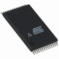
ATMEGA8HVA-4TU Atmel, ATMEGA8HVA-4TU Datasheet - Page 162

ATMEGA8HVA-4TU
Manufacturer Part Number
ATMEGA8HVA-4TU
Description
MCU AVR 8K FLASH 4MHZ 28-TSOP
Manufacturer
Atmel
Series
AVR® ATmegar
Datasheet
1.ATMEGA16HVA-4CKU.pdf
(196 pages)
Specifications of ATMEGA8HVA-4TU
Core Processor
AVR
Core Size
8-Bit
Speed
4MHz
Connectivity
SPI
Peripherals
Brown-out Detect/Reset, POR, PWM, WDT
Number Of I /o
7
Program Memory Size
8KB (4K x 16)
Program Memory Type
FLASH
Eeprom Size
256 x 8
Ram Size
512 x 8
Voltage - Supply (vcc/vdd)
1.8 V ~ 9 V
Data Converters
A/D 5x12b
Oscillator Type
External
Operating Temperature
-20°C ~ 85°C
Package / Case
28-TSOP
For Use With
ATSTK600 - DEV KIT FOR AVR/AVR32ATSTK500 - PROGRAMMER AVR STARTER KIT
Lead Free Status / RoHS Status
Lead free / RoHS Compliant
- Current page: 162 of 196
- Download datasheet (3Mb)
28. Operating Circuit
162
ATmega8HVA/16HVA
Figure 28-1. Operating Circuit Diagram, 2-cell.
Notes:
1. The series resistors on the SPI lines are required for In-System Programming and On-chip
2. PA1 should be connected to SGND when measuring V(RT
3. It is recommended to connect CF1P, CF2N, and CF2P to GND.
Debug support. The value of the series resistor depends on the application. A value of 10k will
ensure that programming and debugging operates correctly, but it must be determined by the
end user that this does not affect the normal operation of the SPI interface.
PA0 should be connected to SGND when measuring V(RT
Rsense
0.010
470
470
470
Rpi
100
Rni
100
RP
RP
RP
RT2
0.1uF
0.1uF
0.1uF
RT1
R1
10K
CP
CP
Ci
PV2
PV1
NV
PI
NI
PA1/ADC1/SGND
PA0/ADC0/SGND
VREF
ATmega8HVA/16HVA
CREF
1 uF
VREFGND
OC
Rcf
1k
VFET
GND
OD
Rdf
1k
RESET
BATT
CRESET
0.1 uF
Rbatt
1k
(MISO) PB3
(MOSI) PB2
(SCK) PB1
(SS) PB0
VREG
CF1N
VCC
PC0
2
1
).
).
CVCC
0.1 uF
Serial communication
CREG
2.2 uF
SPI-communication
8024A–AVR–04/08
+
-
BATT +
BATT -
(1)
Related parts for ATMEGA8HVA-4TU
Image
Part Number
Description
Manufacturer
Datasheet
Request
R

Part Number:
Description:
IC AVR MCU 2.4GHZ XCEIVER 64QFN
Manufacturer:
Atmel
Datasheet:

Part Number:
Description:
Manufacturer:
Atmel
Datasheet:

Part Number:
Description:
MCU ATMEGA644/AT86RF230 40-DIP
Manufacturer:
Atmel
Datasheet:

Part Number:
Description:
BUNDLE ATMEGA644P/AT86RF230 QFN
Manufacturer:
Atmel
Datasheet:

Part Number:
Description:
BUNDLE ATMEGA644P/AT86RF230 TQFP
Manufacturer:
Atmel
Datasheet:

Part Number:
Description:
MCU ATMEGA1281/AT86RF230 64-TQFP
Manufacturer:
Atmel
Datasheet:

Part Number:
Description:
MCU ATMEGA1280/AT86RF230 100TQFP
Manufacturer:
Atmel
Datasheet:

Part Number:
Description:
BUNDLE ATMEGA1280/AT86RF100-TQFP
Manufacturer:
Atmel
Datasheet:

Part Number:
Description:
BUNDLE ATMEGA2560V/AT86RF230-ZU
Manufacturer:
Atmel
Datasheet:

Part Number:
Description:
MCU ATMEGA2561/AT86RF230 64-TQFP
Manufacturer:
Atmel
Datasheet:

Part Number:
Description:
INTERVAL AND WIPE/WASH WIPER CONTROL IC WITH DELAY
Manufacturer:
ATMEL Corporation
Datasheet:

Part Number:
Description:
Low-Voltage Voice-Switched IC for Hands-Free Operation
Manufacturer:
ATMEL Corporation
Datasheet:

Part Number:
Description:
MONOLITHIC INTEGRATED FEATUREPHONE CIRCUIT
Manufacturer:
ATMEL Corporation
Datasheet:

Part Number:
Description:
AM-FM Receiver IC U4255BM-M
Manufacturer:
ATMEL Corporation
Datasheet:


