PIC16LC65B-04/PQ Microchip Technology, PIC16LC65B-04/PQ Datasheet - Page 50
PIC16LC65B-04/PQ
Manufacturer Part Number
PIC16LC65B-04/PQ
Description
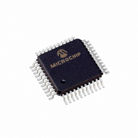
IC MCU OTP 4KX14 PWM 44-MQFP
Manufacturer
Microchip Technology
Series
PIC® 16Cr
Specifications of PIC16LC65B-04/PQ
Core Processor
PIC
Core Size
8-Bit
Speed
4MHz
Connectivity
I²C, SPI, UART/USART
Peripherals
Brown-out Detect/Reset, POR, PWM, WDT
Number Of I /o
33
Program Memory Size
7KB (4K x 14)
Program Memory Type
OTP
Ram Size
192 x 8
Voltage - Supply (vcc/vdd)
2.5 V ~ 5.5 V
Oscillator Type
External
Operating Temperature
0°C ~ 70°C
Package / Case
44-MQFP, 44-PQFP
Processor Series
PIC16LC
Core
PIC
Data Bus Width
8 bit
Data Ram Size
192 B
Interface Type
I2C, SPI, USART
Maximum Clock Frequency
20 MHz
Number Of Programmable I/os
33
Number Of Timers
3
Operating Supply Voltage
2.5 V to 6 V
Maximum Operating Temperature
+ 70 C
Mounting Style
SMD/SMT
3rd Party Development Tools
52715-96, 52716-328, 52717-734
Development Tools By Supplier
ICE2000, DM163022
Minimum Operating Temperature
0 C
Data Rom Size
192 B
Height
2 mm
Length
10 mm
Supply Voltage (max)
5.5 V
Supply Voltage (min)
3.65 V
Width
10 mm
Lead Free Status / RoHS Status
Lead free / RoHS Compliant
Eeprom Size
-
Data Converters
-
Lead Free Status / Rohs Status
Details
Available stocks
Company
Part Number
Manufacturer
Quantity
Price
Company:

Part Number:
PIC16LC65B-04/PQ
Manufacturer:
SIGMADESI
Quantity:
400
Company:
Part Number:
PIC16LC65B-04/PQ
Manufacturer:
Microchip Technology
Quantity:
10 000


PIC16C63A/65B/73B/74B
REGISTER 9-1:
DS30605C-page 50
bit 7-6
bit 5-4
bit 3-0
CCP1CON REGISTER/CCP2CON REGISTER
bit 7
Unimplemented: Read as '0'
CCPxX:CCPxY: PWM Least Significant bits
Capture mode:
Unused
Compare mode:
Unused
PWM mode:
These bits are the two LSbs of the PWM duty cycle. The eight MSbs are found in CCPRxL.
CCPxM3:CCPxM0: CCPx Mode Select bits
0000 = Capture/Compare/PWM disabled (resets CCPx module)
0100 = Capture mode, every falling edge
0101 = Capture mode, every rising edge
0110 = Capture mode, every 4th rising edge
0111 = Capture mode, every 16th rising edge
1000 = Compare mode, set output on match (CCPxIF bit is set)
1001 = Compare mode, clear output on match (CCPxIF bit is set)
1010 = Compare mode, generate software interrupt on match (CCPxIF bit is set, CCPx pin is
1011 = Compare mode, trigger special event (CCPxIF bit is set, CCPx pin is unaffected);
11xx = PWM mode
Legend:
R = Readable bit
-n = Value at POR
U-0
—
unaffected)
CCP1 resets TMR1; CCP2 resets TMR1 and starts an A/D conversion (if A/D module
is enabled)
U-0
—
CCPxX
R/W-0
W = Writable bit
’1’ = Bit is set
CCPxY
R/W-0
CCPxM3
U = Unimplemented bit, read as ‘0’
’0’ = Bit is cleared
R/W-0
CCPxM2 CCPxM1 CCPxM0
R/W-0
2000 Microchip Technology Inc.
x = Bit is unknown
R/W-0
R/W-0
bit 0
Related parts for PIC16LC65B-04/PQ
Image
Part Number
Description
Manufacturer
Datasheet
Request
R

Part Number:
Description:
Manufacturer:
Microchip Technology Inc.
Datasheet:

Part Number:
Description:
IC MCU OTP 4KX14 PWM 44PLCC
Manufacturer:
Microchip Technology
Datasheet:

Part Number:
Description:
IC,MICROCONTROLLER,8-BIT,PIC CPU,CMOS,DIP,40PIN,PLASTIC
Manufacturer:
Microchip Technology
Datasheet:
Part Number:
Description:
IC MCU OTP 4KX14 PWM 40DIP
Manufacturer:
Microchip Technology
Datasheet:
Part Number:
Description:
IC MCU OTP 4KX14 PWM 44PLCC
Manufacturer:
Microchip Technology
Datasheet:

Part Number:
Description:
IC MCU OTP 4KX14 PWM 44-MQFP
Manufacturer:
Microchip Technology
Datasheet:

Part Number:
Description:
IC MCU OTP 4KX14 PWM 44TQFP
Manufacturer:
Microchip Technology
Datasheet:
Part Number:
Description:
IC MCU OTP 4KX14 PWM 44TQFP
Manufacturer:
Microchip Technology
Datasheet:
Part Number:
Description:
IC MIC CTL 4K LP OTP IT 40DIP
Manufacturer:
Microchip Technology
Datasheet:
Part Number:
Description:
IC MIC CTL 4K LP OTP IT 44PLCC
Manufacturer:
Microchip Technology
Datasheet:
Part Number:
Description:
Manufacturer:
Microchip Technology Inc.
Datasheet:
Part Number:
Description:
Manufacturer:
Microchip Technology Inc.
Datasheet:
Part Number:
Description:
Manufacturer:
Microchip Technology Inc.
Datasheet: