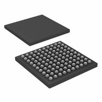
ATXMEGA64A1-C7U Atmel, ATXMEGA64A1-C7U Datasheet - Page 27

ATXMEGA64A1-C7U
Manufacturer Part Number
ATXMEGA64A1-C7U
Description
IC MCU AVR 64KB FLASH 100VFBGA
Manufacturer
Atmel
Series
AVR® XMEGAr
Datasheet
1.ATAVRONEKIT.pdf
(113 pages)
Specifications of ATXMEGA64A1-C7U
Core Processor
AVR
Core Size
8/16-Bit
Speed
32MHz
Connectivity
EBI/EMI, I²C, IrDA, SPI, UART/USART
Peripherals
Brown-out Detect/Reset, DMA, POR, PWM, WDT
Number Of I /o
78
Program Memory Size
64KB (32K x 16)
Program Memory Type
FLASH
Eeprom Size
2K x 8
Ram Size
4K x 8
Voltage - Supply (vcc/vdd)
1.6 V ~ 3.6 V
Data Converters
A/D 16x12b, D/A 4x12b
Oscillator Type
Internal
Operating Temperature
-40°C ~ 85°C
Package / Case
100-VFBGA
Processor Series
XMEGA
Core
AVR
Data Bus Width
8 bit, 16 bit
Data Ram Size
4 KB
Interface Type
SPI, TWI, USART
Maximum Clock Frequency
32 MHz
Number Of Programmable I/os
78
Number Of Timers
8
Operating Supply Voltage
2.5 V
Maximum Operating Temperature
+ 85 C
Mounting Style
SMD/SMT
3rd Party Development Tools
EWAVR, EWAVR-BL
Development Tools By Supplier
ATAVRDRAGON, ATAVRISP2, ATAVRONEKIT
Minimum Operating Temperature
- 40 C
Operating Temperature Range
- 40 C to + 85 C
Lead Free Status / RoHS Status
Lead free / RoHS Compliant
Available stocks
Company
Part Number
Manufacturer
Quantity
Price
14. I/O Ports
14.1
14.2
14.3
8067M–AVR–09/10
Features
Overview
I/O configuration
•
•
•
•
•
•
•
•
•
•
•
•
•
The XMEGA A1 devices have flexible General Purpose I/O Ports. A port consists of up to 8 pins,
ranging from pin 0 to pin 7. The ports implement several functions, including synchronous/asyn-
chronous input sensing, pin change interrupts and configurable output settings. All functions are
individual per pin, but several pins may be configured in a single operation.
All port pins (Pn) have programmable output configuration. In addition, all port pins have an
inverted I/O function. For an input, this means inverting the signal between the port pin and the
pin register. For an output, this means inverting the output signal between the port register and
the port pin. The inverted I/O function can be used also when the pin is used for alternate func-
tions. The port pins also have configurable slew rate limitation to reduce electromagnetic
emission.
Selectable input and output configuration for each pin individually
Flexible pin configuration through dedicated Pin Configuration Register
Synchronous and/or asynchronous input sensing with port interrupts and events
Asynchronous wake-up from all input sensing configurations
Two port interrupts with flexible pin masking
Highly configurable output driver and pull settings:
Optional Slew rate control
Configuration of multiple pins in a single operation
Read-Modify-Write (RMW) support
Toggle/clear/set registers for Output and Direction registers
Clock output on port pin
Event Channel 0 output on port pin 7
Mapping of port registers (virtual ports) into bit accessible I/O memory space
– Sense both edges
– Sense rising edges
– Sense falling edges
– Sense low level
–
–
–
–
–
–
Totem-pole
Pull-up/-down
Wired-AND
Wired-OR
Bus-keeper
Inverted I/O
XMEGA A1
27


