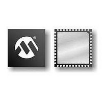
PIC18F47J53T-I/ML Microchip Technology, PIC18F47J53T-I/ML Datasheet - Page 15

PIC18F47J53T-I/ML
Manufacturer Part Number
PIC18F47J53T-I/ML
Description
IC MCU 8BIT 128KB FLASH 44 QFN
Manufacturer
Microchip Technology
Series
PIC® XLP™ 18Fr
Specifications of PIC18F47J53T-I/ML
Program Memory Type
FLASH
Program Memory Size
128KB (64K x 16)
Package / Case
*
Core Processor
PIC
Core Size
8-Bit
Speed
48MHz
Connectivity
I²C, LIN, SPI, UART/USART, USB
Peripherals
Brown-out Detect/Reset, POR, PWM, WDT
Number Of I /o
34
Ram Size
3.8K x 8
Voltage - Supply (vcc/vdd)
2.15 V ~ 3.6 V
Data Converters
A/D 13x10b/12b
Oscillator Type
Internal
Operating Temperature
-40°C ~ 85°C
Processor Series
PIC18F
Core
PIC
Data Bus Width
8 bit
Data Ram Size
3.8 KB
Interface Type
I2C, SPI, USART
Maximum Clock Frequency
48 MHz
Number Of Programmable I/os
22
Number Of Timers
8
Operating Supply Voltage
2.15 V to 3.6 V
Maximum Operating Temperature
+ 85 C
Mounting Style
SMD/SMT
3rd Party Development Tools
52715-96, 52716-328, 52717-734, 52712-325, EWPIC18
Minimum Operating Temperature
- 40 C
Lead Free Status / RoHS Status
Lead free / RoHS Compliant
For Use With
MA180029 - BOARD DEMO PIC18F47J53 FS USB
Eeprom Size
-
Lead Free Status / Rohs Status
Lead free / RoHS Compliant
Available stocks
Company
Part Number
Manufacturer
Quantity
Price
Company:
Part Number:
PIC18F47J53T-I/ML
Manufacturer:
MURATA
Quantity:
640 000
- Current page: 15 of 586
- Download datasheet (6Mb)
FIGURE 1-2:
2010 Microchip Technology Inc.
CTMU
RTCC
Note 1: See Table 1-3 for I/O port pin descriptions.
ECCP1 ECCP2 ECCP3 CCP4 CCP5 CCP6 CCP7 CCP8 CCP9 CCP10
2: The on-chip voltage regulator is always enabled by default.
HLVD
OSC2/CLKO
OSC1/CLKI
ADC
V
USB
PIC18F4XJ53 (44-PIN) BLOCK DIAGRAM
AD<15:0>, A<19:16>
(Multiplexed with PORTD
and PORTE)
Timer0
(16 Kbytes-64 Kbytes)
Table Pointer<21>
inc/dec logic
Program Memory
Instruction Bus <16>
Address Latch
Data Bus<8>
Data Latch
V
DDCORE
State Machine
Control Signals
Generation
Reference
Band Gap
Regulator
Precision
Oscillator
Timer1
INTOSC
Voltage
21
Module
Timing
INTRC
8 MHz
USB
/V
20
CAP
Timer2
8
PCLATU
PCU
V
Program Counter
DD
31-Level Stack
Start-up Timer
Timer3
Decode and
,
ROM Latch
STKPTR
V
Table Latch
Instruction
Watchdog
Brown-out
Power-up
Oscillator
Power-on
Reset
SS
Control
PCLATH
PCH
Reset
Timer
Timer
Preliminary
IR
8
(2)
Timer4
PCL
MCLR
8
PIC18F47J53 FAMILY
Timer5
BSR
BITOP
4
EUSART1
Timer6
3
Data Address<12>
8
Address Latch
Address
Decode
Data Memory
FSR0
FSR1
FSR2
inc/dec
(3.8 Kbytes)
Data Latch
logic
PRODH
8
ALU<8>
12
8 x 8 Multiply
W
Timer8
12
EUSART2
Access
8
Bank
8
PRODL
4
12
Comparators
8
8
8
MSSP1
8
MSSP2
DS39964B-page 15
RC0:RC7
RD0:RD7
RA0:RA7
RB0:RB7
RE0:RE2
USB
PORTC
PORTD
PORTA
PORTB
PORTE
(1)
(1)
(1)
(1)
(1)
Related parts for PIC18F47J53T-I/ML
Image
Part Number
Description
Manufacturer
Datasheet
Request
R

Part Number:
Description:
Manufacturer:
Microchip Technology Inc.
Datasheet:

Part Number:
Description:
Manufacturer:
Microchip Technology Inc.
Datasheet:

Part Number:
Description:
Manufacturer:
Microchip Technology Inc.
Datasheet:

Part Number:
Description:
Manufacturer:
Microchip Technology Inc.
Datasheet:

Part Number:
Description:
Manufacturer:
Microchip Technology Inc.
Datasheet:

Part Number:
Description:
Manufacturer:
Microchip Technology Inc.
Datasheet:

Part Number:
Description:
Manufacturer:
Microchip Technology Inc.
Datasheet:

Part Number:
Description:
Manufacturer:
Microchip Technology Inc.
Datasheet:


