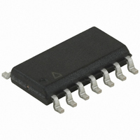
ATTINY24-15SSZ Atmel, ATTINY24-15SSZ Datasheet - Page 178

ATTINY24-15SSZ
Manufacturer Part Number
ATTINY24-15SSZ
Description
MCU AVR 2K FLASH 15MHZ 14-SOIC
Manufacturer
Atmel
Series
AVR® ATtinyr
Datasheet
1.ATTINY24-15SSZ.pdf
(225 pages)
Specifications of ATTINY24-15SSZ
Package / Case
14-SOIC (3.9mm Width), 14-SOL
Voltage - Supply (vcc/vdd)
2.7 V ~ 5.5 V
Operating Temperature
-40°C ~ 125°C
Speed
16MHz
Number Of I /o
12
Eeprom Size
128 x 8
Core Processor
AVR
Program Memory Type
FLASH
Ram Size
128 x 8
Program Memory Size
2KB (2K x 8)
Data Converters
A/D 8x10b
Oscillator Type
Internal
Peripherals
Brown-out Detect/Reset, POR, PWM, WDT
Connectivity
USI
Core Size
8-Bit
Cpu Family
ATtiny
Device Core
AVR
Device Core Size
8b
Frequency (max)
16MHz
Interface Type
SPI/UART
Total Internal Ram Size
128Byte
# I/os (max)
12
Number Of Timers - General Purpose
2
Operating Supply Voltage (typ)
3.3/5V
Operating Supply Voltage (max)
5.5V
Operating Supply Voltage (min)
2.7V
On-chip Adc
8-chx10-bit
Instruction Set Architecture
RISC
Operating Temp Range
-40C to 125C
Operating Temperature Classification
Automotive
Mounting
Surface Mount
Pin Count
14
Package Type
SOIC
Lead Free Status / RoHS Status
Lead free / RoHS Compliant
Available stocks
Company
Part Number
Manufacturer
Quantity
Price
Company:
Part Number:
ATTINY24-15SSZ
Manufacturer:
ATMEL
Quantity:
349
Part Number:
ATTINY24-15SSZ
Manufacturer:
ATTINY
Quantity:
20 000
- Current page: 178 of 225
- Download datasheet (4Mb)
Table 22-1.
Notes:
22.2
Figure 22-1. Maximum Frequency vs. V
178
Symbol
I
I
CC
ACLK
1. All DC Characteristics contained in this data sheet are based on actual silicon characterization of Atmel ATtiny24/44/84 AVR
2. “Max” means the highest value where the pin is guaranteed to be read as low.
3. “Min” means the lowest value where the pin is guaranteed to be read as high.
4. Although each I/O port can sink more than the test conditions (10mA at V
5. Although each I/O port can source more than the test conditions (10mA at V
Speed Grades
Atmel ATtiny24/44/84 [Preliminary]
microcontrollers manufactured in corner run process technology. These values are preliminary values representing design
targets, and will be updated after characterization of actual Automotive silicon.
ditions (non-transient), the following must be observed:
1] The sum of all IOL, for all ports, should not exceed 60mA.
If IOL exceeds the test condition, VOL may exceed the related specification. Pins are not guaranteed to sink current greater
than the listed test condition.
conditions (non-transient), the following must be observed:
1] The sum of all IOH, for all ports, should not exceed 60mA.
If IOH exceeds the test condition, VOH may exceed the related specification. Pins are not guaranteed to source current
greater than the listed test condition. Pull up driving strength of the PB3 RESET pad is weak.
Parameter
Power Supply Current
Power-down mode
Analog Comparator Input
Leakage Current
DC Characteristics
16MHz
8MHz
Active 1MHz, V
Active 4MHz, V
Active 8MHz, V
Idle 1MHz, V
Idle 4MHz, V
Idle 8MHz, V
WDT enabled, V
WDT enabled, V
WDT disabled, V
WDT disabled, V
V
V
Condition
CC
in
T
A
= V
CC
= 5V
= -40°C to 125°C, V
2.7V
CC
/2
CC
CC
CC
Safe Operating
Safe Operating
CC
CC
CC
= 3V
= 3V
= 5V
CC
CC
CC
CC
= 3V
= 3V
= 5V
= 3V
= 5V
= 3V
= 5V
Area
Area
4.5V
CC
= 2.7V to 5.5V (unless otherwise noted)
Min.
-50
5.5V
CC
= 5V, 5mA at V
CC
= 5V, 5mA at V
0.075
Typ.
0.4
1.8
5.0
0.3
1.2
2.5
4.3
5.0
9.0
CC
= 3V) under steady state con-
CC
Max.
10.0
1.5
3.0
0.2
0.5
2.5
= 3V) under steady state
30
50
24
36
50
(1)
(Continued)
7701D–AVR–09/10
Units
mA
mA
mA
mA
mA
mA
µA
µA
µA
µA
nA
Related parts for ATTINY24-15SSZ
Image
Part Number
Description
Manufacturer
Datasheet
Request
R

Part Number:
Description:
Manufacturer:
Atmel Corporation
Datasheet:

Part Number:
Description:
Manufacturer:
Atmel Corporation
Datasheet:

Part Number:
Description:
IC MCU AVR 2K FLASH 20MHZ 20-QFN
Manufacturer:
Atmel
Datasheet:

Part Number:
Description:
IC MCU AVR 2K FLASH 20MHZ 14SOIC
Manufacturer:
Atmel
Datasheet:

Part Number:
Description:
MCU AVR 2K FLASH 15MHZ 20-QFN
Manufacturer:
Atmel
Datasheet:

Part Number:
Description:
IC MCU AVR 2K FLASH 20MHZ 14-DIP
Manufacturer:
Atmel
Datasheet:

Part Number:
Description:
MCU AVR 2KB FLASH 20MHZ 14SOIC
Manufacturer:
Atmel
Datasheet:

Part Number:
Description:
MCU AVR 2KB FLASH 20MHZ 20QFN
Manufacturer:
Atmel
Datasheet:

Part Number:
Description:
IC, MCU, 8BIT, 2K FLASH, 20SOIC
Manufacturer:
Atmel
Datasheet:

Part Number:
Description:
IC, MCU, 8BIT, 2K FLASH, 20PDIP
Manufacturer:
Atmel
Datasheet:

Part Number:
Description:
IC, MCU, 8BIT, 8K FLASH, 20PDIP
Manufacturer:
Atmel
Datasheet:

Part Number:
Description:
IC, MCU, 8BIT, 8K FLASH, 20SOIC
Manufacturer:
Atmel
Datasheet:


