PIC18LF13K22-I/ML Microchip Technology, PIC18LF13K22-I/ML Datasheet - Page 371
PIC18LF13K22-I/ML
Manufacturer Part Number
PIC18LF13K22-I/ML
Description
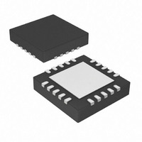
IC PIC MCU FLASH 256KX8 20-QFN
Manufacturer
Microchip Technology
Series
PIC® XLP™ 18Fr
Datasheets
1.PIC18LF13K22-ISS.pdf
(388 pages)
2.PIC18LF13K22-ISS.pdf
(12 pages)
3.PIC18LF13K22-ISS.pdf
(36 pages)
4.PIC18LF14K22-IP.pdf
(382 pages)
Specifications of PIC18LF13K22-I/ML
Program Memory Type
FLASH
Program Memory Size
8KB (4K x 16)
Package / Case
20-VQFN Exposed Pad, 20-HVQFN, 20-SQFN, 20-DHVQFN
Core Processor
PIC
Core Size
8-Bit
Speed
64MHz
Connectivity
I²C, LIN, SPI, UART/USART
Peripherals
Brown-out Detect/Reset, POR, PWM, WDT
Number Of I /o
17
Eeprom Size
256 x 8
Ram Size
256 x 8
Voltage - Supply (vcc/vdd)
1.8 V ~ 3.6 V
Data Converters
A/D 12x10b
Oscillator Type
Internal
Operating Temperature
-40°C ~ 85°C
Processor Series
PIC18LF
Core
PIC
Data Bus Width
8 bit
Data Ram Size
256 B
Interface Type
I2C, MSSP, SPI, USART
Maximum Clock Frequency
32 KHz
Number Of Programmable I/os
18
Number Of Timers
4
Operating Supply Voltage
1.8 V to 3.6 V
Maximum Operating Temperature
+ 125 C
Mounting Style
SMD/SMT
3rd Party Development Tools
52715-96, 52716-328, 52717-734, 52712-325, EWPIC18
Development Tools By Supplier
PG164130, DV164035, DV244005, DV164005
Minimum Operating Temperature
- 40 C
On-chip Adc
10 bit, 12 Channel
Lead Free Status / RoHS Status
Lead free / RoHS Compliant
Lead Free Status / RoHS Status
Lead free / RoHS Compliant, Lead free / RoHS Compliant
Available stocks
Company
Part Number
Manufacturer
Quantity
Price
Company:

Part Number:
PIC18LF13K22-I/ML
Manufacturer:
CAVIUM
Quantity:
155


Device Overview ................................................................... 9
Device Reset Timers......................................................... 247
DEVID1 Register............................................................... 264
DEVID2 Register............................................................... 264
Direct Addressing................................................................ 44
E
ECCPAS Register ............................................................. 125
EECON1 Register ......................................................... 51, 60
Effect on Standard PIC Instructions .................................. 318
Electrical Specifications .................................................... 325
Enhanced Capture/Compare/PWM (ECCP) ..................... 113
Enhanced Universal Synchronous Asynchronous
Errata .................................................................................... 8
EUSART ........................................................................... 175
© 2009 Microchip Technology Inc.
Details on Individual Family Members ........................ 10
Features (28-Pin Devices) .......................................... 11
New Core Features....................................................... 9
Other Special Features ............................................... 10
Oscillator Start-up Timer (OST) ................................ 247
PLL Lock Time-out.................................................... 247
Power-up Timer (PWRT) .......................................... 247
Time-out Sequence................................................... 247
Associated Registers ................................................ 132
Enhanced PWM Mode .............................................. 117
Outputs and Configuration ........................................ 114
Specifications............................................................ 350
Asynchronous Mode ................................................. 177
Baud Rate Generator (BRG)
Clock polarity
Data polarity
Interrupts
Receiver Transmitter (EUSART).............................. 175
Auto-Restart...................................................... 126
Auto-shutdown .................................................. 125
Direction Change in Full-Bridge Output Mode .. 123
Full-Bridge Application ...................................... 121
Full-Bridge Mode .............................................. 121
Half-Bridge Application ..................................... 120
Half-Bridge Application Examples .................... 127
Half-Bridge Mode .............................................. 120
Output Relationships (Active-High and
Output Relationships Diagram .......................... 119
Programmable Dead Band Delay ..................... 127
Shoot-through Current ...................................... 127
Start-up Considerations .................................... 124
12-bit Break Transmit and Receive .................. 194
Associated Registers, Receive ......................... 183
Associated Registers, Transmit ........................ 179
Auto-Wake-up on Break ................................... 192
Baud Rate Generator (BRG) ............................ 187
Clock Accuracy ................................................. 184
Receiver............................................................ 180
Setting up 9-bit Mode with Address Detect....... 182
Transmitter........................................................ 177
Associated Registers ........................................ 187
Auto Baud Rate Detect ..................................... 191
Baud Rate Error, Calculating ............................ 187
Baud Rates, Asynchronous Modes .................. 188
Formulas ........................................................... 187
High Baud Rate Select (BRGH Bit) .................. 187
Synchronous Mode ........................................... 195
Asynchronous Receive ..................................... 180
Asynchronous Transmit .................................... 177
Synchronous Mode ........................................... 195
Active-Low) ............................................... 118
Preliminary
PIC18F1XK22/LF1XK22
Extended Instruction Set
F
Fail-Safe Clock Monitor .............................................. 25, 255
Fast Register Stack ............................................................ 30
Firmware Instructions ....................................................... 271
Flash Program Memory ...................................................... 49
G
General Call Address Support .......................................... 158
GOTO ............................................................................... 292
H
Hardware Multiplier............................................................. 63
I
I/O Ports ............................................................................. 79
I
2
C
Synchronous Master Mode............................... 195, 200
Synchronous Slave Mode
ADDFSR................................................................... 314
ADDULNK ................................................................ 314
and Using MPLAB Tools .......................................... 320
CALLW ..................................................................... 315
Considerations for Use ............................................. 318
MOVSF..................................................................... 315
MOVSS..................................................................... 316
PUSHL...................................................................... 316
SUBFSR ................................................................... 317
SUBULNK................................................................. 317
Syntax....................................................................... 313
Fail-Safe Condition Clearing....................................... 25
Fail-Safe Detection ..................................................... 25
Fail-Safe Operation .................................................... 25
Reset or Wake-up from Sleep .................................... 25
Associated Registers.................................................. 58
Control Registers........................................................ 50
Erase Sequence ......................................................... 55
Erasing ....................................................................... 55
Operation During Code-Protect .................................. 58
Reading ...................................................................... 53
Table Pointer
Table Pointer Boundaries ........................................... 52
Table Reads and Table Writes ................................... 49
Write Sequence .......................................................... 56
Writing To ................................................................... 56
Introduction................................................................. 63
Operation.................................................................... 63
Performance Comparison........................................... 63
Associated Registers................................................ 174
Asynchronous Receive..................................... 181
Asynchronous Transmit.................................... 177
Associated Registers, Receive......................... 199
Associated Registers, Transmit................ 197, 200
Reception ......................................................... 198
Transmission .................................................... 195
Associated Registers, Receive......................... 201
Reception ......................................................... 201
Transmission .................................................... 200
EECON1 and EECON2 ...................................... 50
TABLAT (Table Latch) Register ......................... 52
TBLPTR (Table Pointer) Register....................... 52
Boundaries Based on Operation ........................ 53
Protection Against Spurious Writes .................... 58
Unexpected Termination .................................... 58
Write Verify ......................................................... 58
DS41365C-page 371
Related parts for PIC18LF13K22-I/ML
Image
Part Number
Description
Manufacturer
Datasheet
Request
R

Part Number:
Description:
Manufacturer:
Microchip Technology Inc.
Datasheet:
Part Number:
Description:
Manufacturer:
Microchip Technology Inc.
Datasheet:
Part Number:
Description:
Manufacturer:
Microchip Technology Inc.
Datasheet:
Part Number:
Description:
Manufacturer:
Microchip Technology Inc.
Datasheet:
Part Number:
Description:
Manufacturer:
Microchip Technology Inc.
Datasheet:
Part Number:
Description:
Manufacturer:
Microchip Technology Inc.
Datasheet:
Part Number:
Description:
Manufacturer:
Microchip Technology Inc.
Datasheet:
Part Number:
Description:
Manufacturer:
Microchip Technology Inc.
Datasheet: