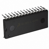
MC908JL16CPE Freescale Semiconductor, MC908JL16CPE Datasheet - Page 42

MC908JL16CPE
Manufacturer Part Number
MC908JL16CPE
Description
IC MCU 16K FLASH 8MHZ 28-DIP
Manufacturer
Freescale Semiconductor
Series
HC08r
Datasheet
1.MC908JL16CFJER.pdf
(230 pages)
Specifications of MC908JL16CPE
Core Processor
HC08
Core Size
8-Bit
Speed
8MHz
Connectivity
I²C, SCI
Peripherals
LED, LVD, POR, PWM
Number Of I /o
23
Program Memory Size
16KB (16K x 8)
Program Memory Type
FLASH
Ram Size
512 x 8
Voltage - Supply (vcc/vdd)
2.7 V ~ 5.5 V
Data Converters
A/D 12x10b
Oscillator Type
Internal
Operating Temperature
-40°C ~ 85°C
Package / Case
28-DIP (0.600", 15.24mm)
Controller Family/series
HC08
No. Of I/o's
23
Ram Memory Size
512Byte
Cpu Speed
8MHz
No. Of Timers
2
Embedded Interface Type
I2C, SCI
Rohs Compliant
Yes
Processor Series
HC08JL
Core
HC08
Data Bus Width
8 bit
Data Ram Size
512 B
Interface Type
SCI
Maximum Clock Frequency
16 MHz
Number Of Programmable I/os
23
Number Of Timers
4
Operating Supply Voltage
2.7 V to 5.5 V
Maximum Operating Temperature
+ 85 C
Mounting Style
Through Hole
Development Tools By Supplier
FSICEBASE, DEMO908JL16E, M68CBL05CE
Minimum Operating Temperature
- 40 C
On-chip Adc
10 bit, 12 Channel
For Use With
DEMO908JL16E - BOARD DEMO FOR MC908JL16
Lead Free Status / RoHS Status
Lead free / RoHS Compliant
Eeprom Size
-
Lead Free Status / Rohs Status
Details
Available stocks
Company
Part Number
Manufacturer
Quantity
Price
Company:
Part Number:
MC908JL16CPE
Manufacturer:
AMS
Quantity:
183
Part Number:
MC908JL16CPE
Manufacturer:
FREESCALE
Quantity:
20 000
- Current page: 42 of 230
- Download datasheet (2Mb)
Configuration and Mask Option Registers (CONFIG and MOR)
3.2 Functional Description
The configuration registers are used in the initialization of various options. The configuration registers can
be written once after each reset. All of the configuration register bits are cleared during reset. Since the
various options affect the operation of the MCU, it is recommended that these registers be written
immediately after reset. The configuration registers are located at $001E and $001F. The configuration
registers may be read at anytime.
The mask option register (MOR) is used to select the oscillator option for the MCU: crystal oscillator or
RC oscillator. The MOR is implemented as a byte in FLASH memory. Hence, writing to the MOR requires
programming the byte.
3.3 Configuration Register 1 (CONFIG1)
COPRS — COP Rate Select Bit
LVID — Low Voltage Inhibit Disable Bit
SSREC — Short Stop Recovery Bit
42
COPRS selects the COP time-out period. Reset clears COPRS. (See
Properly
LVID disables the LVI module. Reset clears LVID. (See
SSREC enables the CPU to exit stop mode with a delay of 32 ICLK cycles instead of a 4096 ICLK cycle
delay.
1 = COP timeout period is (2
0 = COP timeout period is (2
1 = Low voltage inhibit disabled
0 = Low voltage inhibit enabled
1 = Stop mode recovery after 32 ICLK cycles
0 = Stop mode recovery after 4096 ICLK cycles
(COP).)
Address: $001F
The options except LVIT[1:0] are one-time writable by the user after each
reset. The LVIT[1:0] bits are one-time writable by the user only after each
POR (power-on reset). The CONFIG registers are not in the FLASH
memory but are special registers containing one-time writable latches after
each reset. Upon a reset, the CONFIG registers default to predetermined
settings as shown in
Exiting stop mode by pulling reset will result in the long stop recovery. If
using an external crystal, do not set the SSREC bit.
Reset:
Read:
Write:
COPRS
Bit 7
R
0
Figure 3-2. Configuration Register 1 (CONFIG1)
= Reserved
R
6
0
13
18
MC68HC908JL16 Data Sheet, Rev. 1.1
Figure 3-2
– 2
– 2
4
4
) ICLK cycles
) ICLK cycles
R
5
0
and
NOTE
NOTE
LVID
Figure 3-3.
4
0
Chapter 14 Low-Voltage Inhibit
R
3
0
SSREC
2
0
Chapter 13 Computer Operating
STOP
1
0
Freescale Semiconductor
COPD
Bit 0
0
(LVI).)
Related parts for MC908JL16CPE
Image
Part Number
Description
Manufacturer
Datasheet
Request
R
Part Number:
Description:
Manufacturer:
Freescale Semiconductor, Inc
Datasheet:
Part Number:
Description:
Manufacturer:
Freescale Semiconductor, Inc
Datasheet:
Part Number:
Description:
Manufacturer:
Freescale Semiconductor, Inc
Datasheet:
Part Number:
Description:
Manufacturer:
Freescale Semiconductor, Inc
Datasheet:
Part Number:
Description:
Manufacturer:
Freescale Semiconductor, Inc
Datasheet:
Part Number:
Description:
Manufacturer:
Freescale Semiconductor, Inc
Datasheet:
Part Number:
Description:
Manufacturer:
Freescale Semiconductor, Inc
Datasheet:
Part Number:
Description:
Manufacturer:
Freescale Semiconductor, Inc
Datasheet:
Part Number:
Description:
Manufacturer:
Freescale Semiconductor, Inc
Datasheet:
Part Number:
Description:
Manufacturer:
Freescale Semiconductor, Inc
Datasheet:
Part Number:
Description:
Manufacturer:
Freescale Semiconductor, Inc
Datasheet:
Part Number:
Description:
Manufacturer:
Freescale Semiconductor, Inc
Datasheet:
Part Number:
Description:
Manufacturer:
Freescale Semiconductor, Inc
Datasheet:
Part Number:
Description:
Manufacturer:
Freescale Semiconductor, Inc
Datasheet:
Part Number:
Description:
Manufacturer:
Freescale Semiconductor, Inc
Datasheet:


