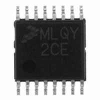
MCL908QY2CDTE Freescale Semiconductor, MCL908QY2CDTE Datasheet - Page 94

MCL908QY2CDTE
Manufacturer Part Number
MCL908QY2CDTE
Description
IC MCU 8BIT 1.5K FLASH 16-TSSOP
Manufacturer
Freescale Semiconductor
Series
HC08r
Datasheet
1.MCL908QY2CDWE.pdf
(182 pages)
Specifications of MCL908QY2CDTE
Core Processor
HC08
Core Size
8-Bit
Speed
2MHz
Peripherals
LVD, POR, PWM
Number Of I /o
13
Program Memory Size
1.5KB (1.5K x 8)
Program Memory Type
FLASH
Ram Size
128 x 8
Voltage - Supply (vcc/vdd)
2.4 V ~ 3.6 V
Data Converters
A/D 4x8b
Oscillator Type
Internal
Operating Temperature
-40°C ~ 85°C
Package / Case
16-TSSOP
Lead Free Status / RoHS Status
Lead free / RoHS Compliant
Eeprom Size
-
Connectivity
-
- Current page: 94 of 182
- Download datasheet (2Mb)
Oscillator Module (OSC)
11.4.3 Oscillator Enable Signal (SIMOSCEN)
The SIMOSCEN signal comes from the system integration module (SIM) and enables/disables either the
XTAL oscillator circuit, the RC oscillator, or the internal oscillator.
11.4.4 XTAL Oscillator Clock (XTALCLK)
XTALCLK is the XTAL oscillator output signal. It runs at the full speed of the crystal (f
) and comes
XCLK
directly from the crystal oscillator circuit.
Figure 11-2
shows only the logical relation of XTALCLK to OSC1
and OSC2 and may not represent the actual circuitry. The duty cycle of XTALCLK is unknown and may
depend on the crystal and other external factors. Also, the frequency and amplitude of XTALCLK can be
unstable at start up.
11.4.5 RC Oscillator Clock (RCCLK)
RCCLK is the RC oscillator output signal. Its frequency is directly proportional to the time constant of
external R and internal C.
Figure 11-3
shows only the logical relation of RCCLK to OSC1 and may not
represent the actual circuitry.
11.4.6 Internal Oscillator Clock (INTCLK)
INTCLK is the internal oscillator output signal. Its nominal frequency is fixed to 4.0 MHz, but it can be also
trimmed using the oscillator trimming feature of the OSCTRIM register (see
11.3.1.1 Internal Oscillator
Trimming).
11.4.7 Oscillator Out 2 (BUSCLKX4)
BUSCLKX4 is the same as the input clock (XTALCLK, RCCLK, or INTCLK). This signal is driven to the
SIM module and is used to determine the COP cycles.
11.4.8 Oscillator Out (BUSCLKX2)
The frequency of this signal is equal to half of the BUSCLKX4, this signal is driven to the SIM for
generation of the bus clocks used by the CPU and other modules on the MCU. BUSCLKX2 will be divided
again in the SIM and results in the internal bus frequency being one fourth of either the XTALCLK,
RCCLK, or INTCLK frequency.
11.5 Low Power Modes
The WAIT and STOP instructions put the MCU in low-power consumption standby modes.
11.5.1 Wait Mode
The WAIT instruction has no effect on the oscillator logic. BUSCLKX2 and BUSCLKX4 continue to drive
to the SIM module.
11.5.2 Stop Mode
The STOP instruction disables either the XTALCLK, the RCCLK, or INTCLK output, hence BUSCLKX2
and BUSCLKX4.
MC68HLC908QY/QT Family Data Sheet, Rev. 3
94
Freescale Semiconductor
Related parts for MCL908QY2CDTE
Image
Part Number
Description
Manufacturer
Datasheet
Request
R
Part Number:
Description:
Manufacturer:
Freescale Semiconductor, Inc
Datasheet:
Part Number:
Description:
Manufacturer:
Freescale Semiconductor, Inc
Datasheet:
Part Number:
Description:
Manufacturer:
Freescale Semiconductor, Inc
Datasheet:
Part Number:
Description:
Manufacturer:
Freescale Semiconductor, Inc
Datasheet:
Part Number:
Description:
Manufacturer:
Freescale Semiconductor, Inc
Datasheet:
Part Number:
Description:
Manufacturer:
Freescale Semiconductor, Inc
Datasheet:
Part Number:
Description:
Manufacturer:
Freescale Semiconductor, Inc
Datasheet:
Part Number:
Description:
Manufacturer:
Freescale Semiconductor, Inc
Datasheet:
Part Number:
Description:
Manufacturer:
Freescale Semiconductor, Inc
Datasheet:
Part Number:
Description:
Manufacturer:
Freescale Semiconductor, Inc
Datasheet:
Part Number:
Description:
Manufacturer:
Freescale Semiconductor, Inc
Datasheet:
Part Number:
Description:
Manufacturer:
Freescale Semiconductor, Inc
Datasheet:
Part Number:
Description:
Manufacturer:
Freescale Semiconductor, Inc
Datasheet:
Part Number:
Description:
Manufacturer:
Freescale Semiconductor, Inc
Datasheet:
Part Number:
Description:
Manufacturer:
Freescale Semiconductor, Inc
Datasheet:


