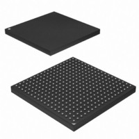
AT91SAM9M10-CU Atmel, AT91SAM9M10-CU Datasheet - Page 16

AT91SAM9M10-CU
Manufacturer Part Number
AT91SAM9M10-CU
Description
IC MCU 16/32BIT ARM9 324TFBGA
Manufacturer
Atmel
Series
AT91SAMr
Specifications of AT91SAM9M10-CU
Core Processor
ARM9
Core Size
16/32-Bit
Speed
400MHz
Connectivity
EBI/EMI, Ethernet, I²C, SPI, SSC, UART/USART, USB
Peripherals
AC'97, DMA, LCD, POR, PWM, WDT
Number Of I /o
160
Program Memory Size
64KB (64K x 8)
Program Memory Type
ROM
Ram Size
128K x 8
Voltage - Supply (vcc/vdd)
0.9 V ~ 1.1 V
Data Converters
A/D 8x10b
Oscillator Type
Internal
Operating Temperature
-40°C ~ 85°C
Package / Case
324-TFBGA
Processor Series
AT91SAMx
Core
ARM926EJ-S
Data Bus Width
32 bit
Data Ram Size
32 KB
Interface Type
2-Wire, SPI, USART
Maximum Clock Frequency
133 MHz
Number Of Programmable I/os
5
Number Of Timers
2 x 16 bit
Operating Supply Voltage
1.65 V to 3.6 V
Maximum Operating Temperature
+ 85 C
Mounting Style
SMD/SMT
3rd Party Development Tools
JTRACE-ARM-2M, MDK-ARM, RL-ARM, ULINK2
Development Tools By Supplier
AT91SAM-ICE, AT91-ISP, AT91SAM9M10-G45-EK
Controller Family/series
AT91
No. Of I/o's
160
Ram Memory Size
64KB
Cpu Speed
400MHz
No. Of Timers
2
Rohs Compliant
Yes
Cpu Family
AT91
Device Core
ARM926EJ-S
Device Core Size
32b
Frequency (max)
400MHz
Total Internal Ram Size
64KB
# I/os (max)
160
Number Of Timers - General Purpose
7
Operating Supply Voltage (typ)
1.8/2.5/3.3V
Operating Supply Voltage (max)
1.1/1.95/3.6V
Operating Supply Voltage (min)
0.9/1.65/1.8/3V
On-chip Adc
8-chx10-bit
Instruction Set Architecture
RISC
Operating Temp Range
-40C to 85C
Operating Temperature Classification
Industrial
Mounting
Surface Mount
Pin Count
324
Package Type
TFBGA
Lead Free Status / RoHS Status
Lead free / RoHS Compliant
Eeprom Size
-
Lead Free Status / Rohs Status
Lead free / RoHS Compliant
Available stocks
Company
Part Number
Manufacturer
Quantity
Price
Company:
Part Number:
AT91SAM9M10-CU
Manufacturer:
Atmel
Quantity:
996
6.2
6.2.1
16
Bus Matrix
AT91SAM9M10
Matrix Masters
The Bus Matrix of the AT91SAM9M10 manages Masters, thus each master can perform an
access concurrently with others, depending on whether the slave it accesses is available.
Each Master has its own decoder, which can be defined specifically for each master. In order to
simplify the addressing, all the masters have the same decodings.
Table 6-1.
Master 0
Master 1
Master 2
Master 3
Master 4
Master 5
Master 6
Master 7
Master 8
Master 9
Master 10
Master 11
• 12-layer Matrix, handling requests from 11 masters
• Programmable Arbitration strategy
• Burst Management
• One Address Decoder provided per Master
• Boot Mode Select
• Remap Command
– Fixed-priority Arbitration
– Round-Robin Arbitration, either with no default master, last accessed default master
– Breaking with Slot Cycle Limit Support
– Undefined Burst Length Support
– Three different slaves may be assigned to each decoded memory area: one for
– Non-volatile Boot Memory can be internal ROM or external memory on EBI_NCS0
– Selection is made by General purpose NVM bit sampled at reset
– Allows Remapping of an Internal SRAM in Place of the Boot Non-Volatile Memory
– Allows Handling of Dynamic Exception Vectors
or fixed default master
internal ROM boot, one for internal flash boot, one after remap
(ROM or External Flash)
List of Bus Matrix Masters
ARM926
ARM926 Data
Peripheral DMA Controller (PDC)
LCD DMA
Ethernet MAC DMA
USB Device High Speed DMA
USB Host High Speed EHCI DMA
Video Decoder
USB HOST OHCI
DMA
DMA
ISI Controller DMA
™
Instruction
6355BS–ATARM–21-Jun-10


