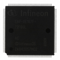
SAF-XE167F-72F66L AC Infineon Technologies, SAF-XE167F-72F66L AC Datasheet - Page 78

SAF-XE167F-72F66L AC
Manufacturer Part Number
SAF-XE167F-72F66L AC
Description
IC MCU 16BIT FLASH PG-LQFP-144
Manufacturer
Infineon Technologies
Series
XE16xr
Datasheet
1.SAF-XE167K-96F66L_AC.pdf
(122 pages)
Specifications of SAF-XE167F-72F66L AC
Core Processor
C166SV2
Core Size
16-Bit
Speed
66MHz
Connectivity
CAN, EBI/EMI, I²C, LIN, SPI, SSC, UART/USART, USI
Peripherals
I²S, POR, PWM, WDT
Number Of I /o
118
Program Memory Size
576KB (576K x 8)
Program Memory Type
FLASH
Ram Size
50K x 8
Voltage - Supply (vcc/vdd)
3 V ~ 5.5 V
Data Converters
A/D 24x10b
Oscillator Type
Internal
Operating Temperature
-40°C ~ 85°C
Package / Case
144-LFQFP
Data Bus Width
16 bit
Data Ram Size
32 KB
Interface Type
CAN
Maximum Clock Frequency
66 MHz
Number Of Programmable I/os
118
Number Of Timers
11
Maximum Operating Temperature
+ 85 C
Mounting Style
SMD/SMT
Minimum Operating Temperature
- 40 C
On-chip Adc
10 bit, 24 Channel
Lead Free Status / RoHS Status
Lead free / RoHS Compliant
Eeprom Size
-
Lead Free Status / Rohs Status
Details
Other names
FXE167F72F66LACXP
SAF-XE167F-72F66LACIN
SP000363813
SAF-XE167F-72F66LACIN
SP000363813
4.2
These parameters are static or average values that may be exceeded during switching
transitions (e.g. output current).
The XE167 can operate within a wide supply voltage range from 3.0 V to 5.5 V.
However, during operation this supply voltage must remain within 10 percent of the
selected nominal supply voltage. It cannot vary across the full operating voltage range.
Because of the supply voltage restriction and because electrical behavior depends on
the supply voltage, the parameters are specified separately for the upper and the lower
voltage range.
During operation, the supply voltages may only change with a maximum speed of
dV/dt < 1 V/ms.
Leakage current is strongly dependent on the operating temperature and the voltage
level at the respective pin. The maximum values in the following tables apply under worst
case conditions, i.e. maximum temperature and an input level equal to the supply
voltage.
The value for the leakage current in an application can be determined by using the
respective leakage derating formula (see tables) with values from that application.
The pads of the XE167 are designed to operate in various driver modes. The DC
parameter specifications refer to the current limits in
Table 13
Port Output Driver
Mode
Strong driver
Medium driver
Weak driver
1) An output current above |
Data Sheet
For any group of 16 neighboring output pins, the total output current in each direction (Σ
remain below 50 mA.
DC Parameters
Current Limits for Port Output Drivers
I
OXnom
Maximum Output Current
(
V
10 mA
4.0 mA
0.5 mA
I
OLmax
DDP
| may be drawn from up to three pins at the same time.
≥ 4.5 V
, -
I
OHmax
)
1)
V
10 mA
2.5 mA
0.5 mA
DDP
76
< 4.5 V
Table
Nominal Output Current
(
V
2.5 mA
1.0 mA
0.1 mA
I
XE166 Family Derivatives
DDP
OLnom
13.
≥ 4.5 V
, -
Electrical Parameters
I
OHnom
)
V
2.5 mA
1.0 mA
0.1 mA
I
OL
DDP
V2.1, 2008-08
and Σ-
< 4.5 V
XE167x
I
OH
) must


