MC908GP32CPE Freescale Semiconductor, MC908GP32CPE Datasheet - Page 51
MC908GP32CPE
Manufacturer Part Number
MC908GP32CPE
Description
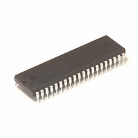
IC MCU 8MHZ 32K FLASH 40-DIP
Manufacturer
Freescale Semiconductor
Series
HC08r
Datasheet
1.MC908GP32CFBE.pdf
(266 pages)
Specifications of MC908GP32CPE
Core Processor
HC08
Core Size
8-Bit
Speed
8MHz
Connectivity
SCI, SPI
Peripherals
LVD, POR, PWM
Number Of I /o
33
Program Memory Size
32KB (32K x 8)
Program Memory Type
FLASH
Ram Size
512 x 8
Voltage - Supply (vcc/vdd)
2.7 V ~ 5.5 V
Data Converters
A/D 8x8b
Oscillator Type
Internal
Operating Temperature
-40°C ~ 85°C
Package / Case
40-DIP (0.600", 15.24mm)
Processor Series
HC08GP
Core
HC08
Data Bus Width
8 bit
Data Ram Size
512 B
Interface Type
SCI, SPI
Maximum Clock Frequency
8 MHz
Number Of Programmable I/os
33
Number Of Timers
4
Maximum Operating Temperature
+ 85 C
Mounting Style
Through Hole
Development Tools By Supplier
FSICEBASE, DEMO908GZ60E, M68CBL05CE, M68EML08GPGTE
Minimum Operating Temperature
- 40 C
On-chip Adc
8 bit, 8 Channel
Lead Free Status / RoHS Status
Lead free / RoHS Compliant
Eeprom Size
-
Lead Free Status / Rohs Status
Details
Available stocks
Company
Part Number
Manufacturer
Quantity
Price
Company:

Part Number:
MC908GP32CPE
Manufacturer:
NXP
Quantity:
9 282
Part Number:
MC908GP32CPE
Manufacturer:
FREESCALE
Quantity:
20 000


3.13 Timebase Module (TBM)
3.13.1 Wait Mode
The timebase module remains active after execution of the WAIT instruction. In wait mode, the timebase
register is not accessible by the CPU.
If the timebase functions are not required during wait mode, reduce the power consumption by stopping
the timebase before enabling the WAIT instruction.
3.13.2 Stop Mode
The timebase module may remain active after execution of the STOP instruction if the oscillator has been
enabled to operate during stop mode through the OSCSTOPEN bit in the CONFIG register. The timebase
module can be used in this mode to generate a periodic wakeup from stop mode.
If the oscillator has not been enabled to operate in stop mode, the timebase module will not be active
during stop mode. In stop mode, the timebase register is not accessible by the CPU.
If the timebase functions are not required during stop mode, reduce the power consumption by stopping
the timebase before enabling the STOP instruction.
3.14 Exiting Wait Mode
These events restart the CPU clock and load the program counter with the reset vector or with an interrupt
vector:
Freescale Semiconductor
•
•
•
•
•
•
•
•
•
External reset — A logic 0 on the RST pin resets the MCU and loads the program counter with the
contents of locations $FFFE and $FFFF.
External interrupt — A high-to-low transition on an external interrupt pin (IRQ pin) loads the
program counter with the contents of locations: $FFFA and $FFFB; IRQ pin.
Break interrupt — A break interrupt loads the program counter with the contents of $FFFC and
$FFFD.
Computer operating properly module (COP) reset — A timeout of the COP counter resets the MCU
and loads the program counter with the contents of $FFFE and $FFFF.
Low-voltage inhibit module (LVI) reset — A power supply voltage below the V
MCU and loads the program counter with the contents of locations $FFFE and $FFFF.
Clock generator module (CGM) interrupt — A CPU interrupt request from the phase-locked loop
(PLL) loads the program counter with the contents of $FFF8 and $FFF9.
Keyboard module (KBI) interrupt — A CPU interrupt request from the KBI module loads the
program counter with the contents of $FFE0 and $FFE1.
Timer 1 interface module (TIM1) interrupt — A CPU interrupt request from the TIM1 loads the
program counter with the contents of:
–
–
–
Timer 2 interface module (TIM2) interrupt — A CPU interrupt request from the TIM2 loads the
program counter with the contents of:
–
–
–
$FFF2 and $FFF3; TIM1 overflow
$FFF4 and $FFF5; TIM1 channel 1
$FFF6 and $FFF7; TIM1 channel 0
$FFEC and $FFED; TIM2 overflow
$FFEE and $FFEF; TIM2 channel 1
$FFF0 and $FFF1; TIM2 channel 0
MC68HC908GP32 Data Sheet, Rev. 10
Timebase Module (TBM)
tripf
voltage resets the
51
Related parts for MC908GP32CPE
Image
Part Number
Description
Manufacturer
Datasheet
Request
R

Part Number:
Description:
Manufacturer:
Freescale Semiconductor, Inc
Datasheet:
Part Number:
Description:
Manufacturer:
Freescale Semiconductor, Inc
Datasheet:
Part Number:
Description:
Manufacturer:
Freescale Semiconductor, Inc
Datasheet:
Part Number:
Description:
Manufacturer:
Freescale Semiconductor, Inc
Datasheet:
Part Number:
Description:
Manufacturer:
Freescale Semiconductor, Inc
Datasheet:
Part Number:
Description:
Manufacturer:
Freescale Semiconductor, Inc
Datasheet:
Part Number:
Description:
Manufacturer:
Freescale Semiconductor, Inc
Datasheet:
Part Number:
Description:
Manufacturer:
Freescale Semiconductor, Inc
Datasheet:
Part Number:
Description:
Manufacturer:
Freescale Semiconductor, Inc
Datasheet:
Part Number:
Description:
Manufacturer:
Freescale Semiconductor, Inc
Datasheet:
Part Number:
Description:
Manufacturer:
Freescale Semiconductor, Inc
Datasheet:
Part Number:
Description:
Manufacturer:
Freescale Semiconductor, Inc
Datasheet:
Part Number:
Description:
Manufacturer:
Freescale Semiconductor, Inc
Datasheet:
Part Number:
Description:
Manufacturer:
Freescale Semiconductor, Inc
Datasheet:
Part Number:
Description:
Manufacturer:
Freescale Semiconductor, Inc
Datasheet: