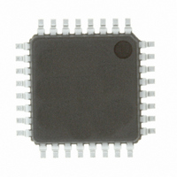
R5F21132FP#U0 Renesas Electronics America, R5F21132FP#U0 Datasheet - Page 69

R5F21132FP#U0
Manufacturer Part Number
R5F21132FP#U0
Description
IC R8C MCU FLASH 8K 32LQFP
Manufacturer
Renesas Electronics America
Series
M16C™ M16C/R8C/Tiny/13r
Datasheets
1.R5F211A2SPU0.pdf
(300 pages)
2.R5F21132FPU0.pdf
(33 pages)
3.R5F21132FPU0.pdf
(226 pages)
Specifications of R5F21132FP#U0
Core Processor
R8C
Core Size
16-Bit
Speed
20MHz
Connectivity
SIO, UART/USART
Peripherals
LED, POR, Voltage Detect, WDT
Number Of I /o
22
Program Memory Size
8KB (8K x 8)
Program Memory Type
FLASH
Ram Size
512 x 8
Voltage - Supply (vcc/vdd)
2.7 V ~ 5.5 V
Data Converters
A/D 12x10b
Oscillator Type
Internal
Operating Temperature
-20°C ~ 85°C
Package / Case
32-LQFP
For Use With
R0K521134S000BE - KIT EVAL STARTER FOR R8C/13R0E521134EPB00 - KIT EMULATOR PROBE FOR PC7501R0E521134CPE00 - EMULATOR COMPACT R8C/13
Lead Free Status / RoHS Status
Lead free / RoHS Compliant
Eeprom Size
-
Available stocks
Company
Part Number
Manufacturer
Quantity
Price
- Current page: 69 of 226
- Download datasheet (3Mb)
R8C/13 Group
Rev.1.20
REJ09B0111-0120
Figure 10.5 Interrupt Response Time
Table 10.5 IPL Level That Is Set to IPL When A Software or Special Interrupt Is Accepted
Watchdog timer, oscillation stop detection, voltage detection
Software, address match, single-step
• Variation of IPL when Interrupt Request is Accepted
• Interrupt Response Time
Jan 27, 2006
When a maskable interrupt request is accepted, the interrupt priority level of the accepted interrupt is
set in the IPL.
When a software interrupt or special interrupt request is accepted, one of the interrupt priority levels
listed in Table 10.5 is set in the IPL. Shown in Table 10.5 are the IPL values of software and special
interrupts when they are accepted.
Interrupt request generated
Figure 10.5 shows the interrupt response time. The interrupt response or interrupt acknowledge time
denotes a time from when an interrupt request is generated till when the first instruction in the inter-
rupt routine is executed. Specifically, it consists of a time from when an interrupt request is gener-
ated till when the instruction then executing is completed (see #a in Figure 10.5) and a time during
which the interrupt sequence is executed (20 cycles, see #b in Figure 10.5).
(a) A time from when an interrupt request is generated till when the instruction then
(b) 21 cycles for address match and single-step interrupts.
executing is completed. The length of this time varies with the instruction being
executed. The DIVX instruction requires the longest time, which is equal to 30 cycles
(without wait state, the divisor being a register).
Interrupt factors
page 56 of 205
Instruction
(a)
Interrupt response time
Interrupt request acknowledged
Interrupt sequence
20 cycles (b)
interrupt routine
Instruction in
Level that is set to IPL
Not changed
7
10.1 Interrupt Overview
Time
Related parts for R5F21132FP#U0
Image
Part Number
Description
Manufacturer
Datasheet
Request
R

Part Number:
Description:
KIT STARTER FOR M16C/29
Manufacturer:
Renesas Electronics America
Datasheet:

Part Number:
Description:
KIT STARTER FOR R8C/2D
Manufacturer:
Renesas Electronics America
Datasheet:

Part Number:
Description:
R0K33062P STARTER KIT
Manufacturer:
Renesas Electronics America
Datasheet:

Part Number:
Description:
KIT STARTER FOR R8C/23 E8A
Manufacturer:
Renesas Electronics America
Datasheet:

Part Number:
Description:
KIT STARTER FOR R8C/25
Manufacturer:
Renesas Electronics America
Datasheet:

Part Number:
Description:
KIT STARTER H8S2456 SHARPE DSPLY
Manufacturer:
Renesas Electronics America
Datasheet:

Part Number:
Description:
KIT STARTER FOR R8C38C
Manufacturer:
Renesas Electronics America
Datasheet:

Part Number:
Description:
KIT STARTER FOR R8C35C
Manufacturer:
Renesas Electronics America
Datasheet:

Part Number:
Description:
KIT STARTER FOR R8CL3AC+LCD APPS
Manufacturer:
Renesas Electronics America
Datasheet:

Part Number:
Description:
KIT STARTER FOR RX610
Manufacturer:
Renesas Electronics America
Datasheet:

Part Number:
Description:
KIT STARTER FOR R32C/118
Manufacturer:
Renesas Electronics America
Datasheet:

Part Number:
Description:
KIT DEV RSK-R8C/26-29
Manufacturer:
Renesas Electronics America
Datasheet:

Part Number:
Description:
KIT STARTER FOR SH7124
Manufacturer:
Renesas Electronics America
Datasheet:

Part Number:
Description:
KIT STARTER FOR H8SX/1622
Manufacturer:
Renesas Electronics America
Datasheet:

Part Number:
Description:
KIT DEV FOR SH7203
Manufacturer:
Renesas Electronics America
Datasheet:


