EG87C51FA1SF76 Intel, EG87C51FA1SF76 Datasheet - Page 9
EG87C51FA1SF76
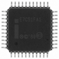
Manufacturer Part Number
EG87C51FA1SF76
Description
IC MCU 8-BIT 8K 16MHZ OTP 44MQFP
Manufacturer
Intel
Series
87Cr
Datasheet
1.EE80C51FA24SF88.pdf
(20 pages)
Specifications of EG87C51FA1SF76
Core Processor
MCS 51
Core Size
8-Bit
Speed
16MHz
Connectivity
SIO
Peripherals
PWM, WDT
Number Of I /o
32
Program Memory Size
8KB (8K x 8)
Program Memory Type
OTP
Ram Size
256 x 8
Voltage - Supply (vcc/vdd)
4.5 V ~ 5.5 V
Oscillator Type
External
Operating Temperature
-40°C ~ 85°C
Package / Case
44-MQFP, 44-PQFP
Lead Free Status / RoHS Status
Lead free / RoHS Compliant
Eeprom Size
-
Data Converters
-
Other names
864517
Available stocks
Company
Part Number
Manufacturer
Quantity
Price
Company:

Part Number:
EG87C51FA1SF76
Manufacturer:
Maxim
Quantity:
32


DC CHARACTERISTICS
All parameter values apply to all devices unless otherwise indicated (Continued)
NOTES
1 Capacitive loading on Ports 0 and 2 may cause noise pulses above 0 4V to be superimposed on the V
Ports 1 2 and 3 The noise is due to external bus capacitance discharging into the Port 0 and Port 2 pins when these pins
change from 1 to 0 In applications where capacitance loading exceeds 100 pF the noise pulses on these signals may
exceed 0 8V It may be desirable to qualify ALE or other signals with a Schmitt Trigger or CMOS-level input logic
2 Capacitive loading on Ports 0 and 2 cause the V
address lines are stabilizing
3 See Figures 6–9 for test conditions Minimum V
4 Typicals are based on limited number of samples and are not guaranteed The values listed are at room temperature and 5V
5 Under steady state (non-transient) conditions I
If I
than the listed test conditions
Note
I
Maximum I
Maximum I
Maximum total I
CC
Symbol
I
I
RRST
CIO
I
OL
LI
TL
CC
max at 33 MHz is at 5V
exceeds the test condition V
OL
OL
per port pin
per 8-bit port -
Input leakage Current (Port 0)
Logical 1 to 0 Transition Current
(Ports 1 2 and 3)
Express
Commercial
RST Pulldown Resistor
Pin Capacitance
Power Supply Current
OL
Active Mode
Idle Mode
Power Down Mode
At 12 MHz (Figure 5)
At 16 MHz
At 24 MHz
At 33 MHz
At 12 MHz (Figure 5)
At 16 MHz
At 24 MHz
At 33 MHz
for all output pins
Ports 1 2 and 3
Parameter
g
10% V
Port 0
OL
Figure 5 8XC51FA FB FC I
(Over Operating Conditions)
may exceed the related specification Pins are not guaranteed to sink current greater
CC
while I
26 mA
10 mA
15 mA
71 mA
OL
CC
CC
OH
must be externally limited as follows
max at 24 MHz and below is at 5V
for power down is 2V
on ALE and PSEN to drop below the 0 9 V
Min
40
(Note 4)
Typical
CC
10
15
20
28
35
5
6
7
7
5
vs Frequency
b
b
Max
g
13 5
225
7 5
9 5
30
38
56
56
15
75
750
650
10
g
20% V
Units
K
mA
mA
mA
mA
mA
mA
mA
mA
pF
A
A
A
CC
CC
specification when the
Test Conditions
V
V
(Note 3)
IN
IN
1MHz 25 C
272322 –5
e
e
OL
s of ALE and
V
2V
8XC51FX
IL
or V
IH
9
Related parts for EG87C51FA1SF76
Image
Part Number
Description
Manufacturer
Datasheet
Request
R

Part Number:
Description:
Microprocessor: Intel Celeron M Processor 320 and Ultra Low Voltage Intel Celeron M Processor at 600MHz
Manufacturer:
Intel Corporation
Part Number:
Description:
Intel 82550 Fast Ethernet Multifunction PCI/CardBus Controller
Manufacturer:
Intel Corporation
Datasheet:
Part Number:
Description:
Intel StrataFlash memory 32 Mbit. Access speed 120 ns
Manufacturer:
Intel Corporation
Datasheet:
Part Number:
Description:
Intel StrataFlash memory 32 Mbit. Access speed 120 ns
Manufacturer:
Intel Corporation
Datasheet:
Part Number:
Description:
Intel StrataFlash memory 64 Mbit. Access speed 150 ns
Manufacturer:
Intel Corporation
Datasheet:
Part Number:
Description:
Intel StrataFlash memory 32 Mbit. Access speed 100 ns
Manufacturer:
Intel Corporation
Datasheet:
Part Number:
Description:
DA28F640J5A-1505 Volt Intel StrataFlash Memory
Manufacturer:
Intel Corporation
Datasheet:
Part Number:
Description:
5 Volt Intel StrataFlash?? Memory
Manufacturer:
Intel Corporation
Datasheet:
Part Number:
Description:
5 Volt Intel StrataFlash?? Memory
Manufacturer:
Intel Corporation
Part Number:
Description:
Intel 6300ESB I/O Controller Hub
Manufacturer:
Intel Corporation
Datasheet:
Part Number:
Description:
Intel 82801DB I/O Controller Hub (ICH4), Pb-Free SLI
Manufacturer:
Intel Corporation
Datasheet:
Part Number:
Description:
Intel 82801FB I/O Controller Hub (ICH6)
Manufacturer:
Intel Corporation
Datasheet:
Part Number:
Description:
Intel Strataflash Memory28F128J3 28F640J3 28F320J3
Manufacturer:
Intel Corporation
Datasheet:
Part Number:
Description:
Controllers, Intel 430TX PCIset: 82439TX System Controller (MTXC)
Manufacturer:
Intel Corporation