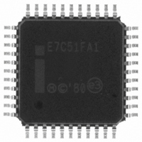
EG87C51FA1SF76 Intel, EG87C51FA1SF76 Datasheet - Page 18

EG87C51FA1SF76
Manufacturer Part Number
EG87C51FA1SF76
Description
IC MCU 8-BIT 8K 16MHZ OTP 44MQFP
Manufacturer
Intel
Series
87Cr
Datasheet
1.EE80C51FA24SF88.pdf
(20 pages)
Specifications of EG87C51FA1SF76
Core Processor
MCS 51
Core Size
8-Bit
Speed
16MHz
Connectivity
SIO
Peripherals
PWM, WDT
Number Of I /o
32
Program Memory Size
8KB (8K x 8)
Program Memory Type
OTP
Ram Size
256 x 8
Voltage - Supply (vcc/vdd)
4.5 V ~ 5.5 V
Oscillator Type
External
Operating Temperature
-40°C ~ 85°C
Package / Case
44-MQFP, 44-PQFP
Lead Free Status / RoHS Status
Lead free / RoHS Compliant
Eeprom Size
-
Data Converters
-
Other names
864517
Available stocks
Company
Part Number
Manufacturer
Quantity
Price
Company:
Part Number:
EG87C51FA1SF76
Manufacturer:
Maxim
Quantity:
32
8XC51FX
Encryption Array
Within the EPROM array are 64 bytes of Encryption
Array that are initially unprogrammed (all 1’s) Every
time that a byte is addressed during a verify 6 ad-
dress lines are used to select a byte of the Encryp-
tion Array This byte is then exclusive-NOR’ed
(XNOR) with the code byte creating an Encryption
Verify byte The algorithm with the array in the un-
programmed state (all 1’s) will return the code in its
original unmodified form For programming the En-
cryption Array refer to Table 4 (Programming the
EPROM)
When using the encryption array one important fac-
tor needs to be considered If a code byte has the
value 0FFH verifying the byte will produce the en-
cryption byte value lf a large block (
code is left unprogrammed a verification routine will
display the contents of the encryption array For this
reason all unused code bytes should be pro-
grammed with some value other than 0FFH and not
all of them the same value This will ensure maxi-
mum program protection
Program Lock Bits
The 87C51FX has 3 programmable lock bits that
when programmed according to Table 5 will provide
different levels of protection for the on-chip code
and data
Erasing the EPROM also erases the encryption ar-
ray and the program lock bits returning the part to
full functionality
Reading the Signature Bytes
The 87C51FX has 3 signature bytes in locations
30H 31H and 60H The 83C51FA has 2 signature
18
l
64 bytes) of
bytes in locations 30H and 31H To read these bytes
follow the procedure for EPROM verify but activate
the control lines provided in Table 4 for Read Signa-
ture Byte
Erasure Characteristics (Windowed
Packages Only)
Erasure of the EPROM begins to occur when the
chip is exposed to light with wavelength shorter than
approximately 4 000 Angstroms Since sunlight and
fluorescent lighting have wavelengths in this range
exposure to these light sources over an extended
time (about 1 week in sunlight or 3 years in room-
level fluorescent lighting) could cause inadvertent
erasure If an application subjects the device to this
type of exposure it is suggested that an opaque la-
bel be placed over the window
The recommended erasure procedure is exposure
to ultraviolet light (at 2537 Angstroms) to an integrat-
ed dose of at least 15 W-sec cm Exposing the
EPROM to an ultraviolet lamp of 12 000 W cm rat-
ing for 30 minutes at a distance of about 1 inch
should be sufficient
Erasure leaves all the EPROM Cells in a 1’s state
Location
30H
31H
60H
83C51FA
87C51FA
83C51FB
87C51FB
83C51FC
87C51FC
Device
All
All
7AH FAH
7BH FBH
7CH FCH
Contents
FAH
FBH
FCH
89H
58H


