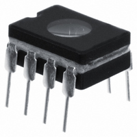
PIC12CE673/JW Microchip Technology, PIC12CE673/JW Datasheet - Page 474

PIC12CE673/JW
Manufacturer Part Number
PIC12CE673/JW
Description
IC MCU EPROM 1KX14 A/D&EE 8CDIP
Manufacturer
Microchip Technology
Series
PIC® 12Cr
Datasheets
1.PIC16F688T-ISL.pdf
(688 pages)
2.PIC12CE673-10P.pdf
(129 pages)
3.PIC12CE673-10P.pdf
(3 pages)
4.PIC12CE673-10P.pdf
(14 pages)
5.PIC12CE673-10P.pdf
(12 pages)
Specifications of PIC12CE673/JW
Core Processor
PIC
Core Size
8-Bit
Speed
10MHz
Peripherals
POR, WDT
Number Of I /o
5
Program Memory Size
1.75KB (1K x 14)
Program Memory Type
EPROM, UV
Eeprom Size
16 x 8
Ram Size
128 x 8
Voltage - Supply (vcc/vdd)
3 V ~ 5.5 V
Data Converters
A/D 4x8b
Oscillator Type
Internal
Operating Temperature
0°C ~ 70°C
Package / Case
8-CDIP (0.300", 7.62mm) Window
For Use With
ISPICR1 - ADAPTER IN-CIRCUIT PROGRAMMINGAC124001 - MODULE SKT PROMATEII 8DIP/SOIC
Lead Free Status / RoHS Status
Contains lead / RoHS non-compliant
Connectivity
-
- PIC16F688T-ISL PDF datasheet
- PIC12CE673-10P PDF datasheet #2
- PIC12CE673-10P PDF datasheet #3
- PIC12CE673-10P PDF datasheet #4
- PIC12CE673-10P PDF datasheet #5
- Current page: 474 of 688
- Download datasheet (3Mb)
PICmicro MID-RANGE MCU FAMILY
25.7
DS31025A-page 25-16
Pin
COM0
Pin
COM1
Pin
COM3
Pin
SEG0
Operation During Sleep
interrupted
frame
SLEEP instruction execution
The LCD module can operate during sleep. The selection is controlled by bit SLPEN
(LCDCON<6>). Setting the SLPEN bit allows the LCD module to go to sleep. Clearing the
SLPEN bit allows the module to continue to operate during sleep.
If a SLEEP instruction is executed and SLPEN = '1', the LCD module will cease all functions and
go into a very low current consumption mode. The module will stop operation immediately and
drive the minimum LCD voltage on both segment and common lines.
operation. To ensure that the LCD completes the frame, the SLEEP instruction should be exe-
cuted immediately after a LCD frame boundary. The LCD interrupt can be used to determine the
frame boundary. See
If a SLEEP instruction is executed and SLPEN = '0', the module will continue to display the current
contents of the LCDD registers. To allow the module to continue operation while in sleep, the
clock source must be either the internal RC oscillator or Timer1 external oscillator. While in sleep,
the LCD data cannot be changed. The LCD module current consumption will not decrease in this
mode, however the overall consumption of the device will be lower due to shutdown of the core
and other peripheral functions.
Figure 25-9:Sleep Entry/exit When SLPEN = 1 or CS1:CS0 = 00
Note:
The internal RC oscillator or external Timer1 oscillator must be used to operate the
LCD module during sleep.
25.4 “LCD Interrupts”
for the formulas to calculate the delay.
Wake-up
1997 Microchip Technology Inc.
Figure 25-9
shows this
3/3V
2/3V
1/3V
0/3V
3/3V
2/3V
1/3V
0/3V
3/3V
2/3V
1/3V
0/3V
3/3V
2/3V
1/3V
0/3V
Related parts for PIC12CE673/JW
Image
Part Number
Description
Manufacturer
Datasheet
Request
R

Part Number:
Description:
8-Pin/ 8-Bit CMOS Microcontroller with EEPROM Data Memory
Manufacturer:
Microchip Technology

Part Number:
Description:
IC, 8BIT MCU, PIC12, 32MHZ, DFN-8
Manufacturer:
Microchip Technology
Datasheet:

Part Number:
Description:
IC, 8BIT MCU, PIC12, 32MHZ, DFN-8
Manufacturer:
Microchip Technology
Datasheet:

Part Number:
Description:
Manufacturer:
Microchip Technology Inc.
Datasheet:

Part Number:
Description:
Manufacturer:
Microchip Technology Inc.
Datasheet:

Part Number:
Description:
Manufacturer:
Microchip Technology Inc.
Datasheet:

Part Number:
Description:
Manufacturer:
Microchip Technology Inc.
Datasheet:

Part Number:
Description:
Manufacturer:
Microchip Technology Inc.
Datasheet:

Part Number:
Description:
Manufacturer:
Microchip Technology Inc.
Datasheet:

Part Number:
Description:
Manufacturer:
Microchip Technology Inc.
Datasheet:


