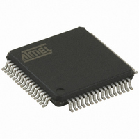
AT89C51CC03U-RDRIM Atmel, AT89C51CC03U-RDRIM Datasheet - Page 86

AT89C51CC03U-RDRIM
Manufacturer Part Number
AT89C51CC03U-RDRIM
Description
IC 8051 MCU FLASH 64K 64VQFP
Manufacturer
Atmel
Series
AT89C CANr
Datasheets
1.AT89C51CC03C-S3RIM.pdf
(198 pages)
2.AT89C51CC03C-S3RIM.pdf
(32 pages)
3.AT89C51CC03C-S3RIM.pdf
(27 pages)
4.AT89C51CC03C-S3RIM.pdf
(184 pages)
Specifications of AT89C51CC03U-RDRIM
Core Processor
8051
Core Size
8-Bit
Speed
40MHz
Connectivity
CAN, SPI, UART/USART
Peripherals
POR, PWM, WDT
Number Of I /o
36
Program Memory Size
64KB (64K x 8)
Program Memory Type
FLASH
Eeprom Size
2K x 8
Ram Size
2.25K x 8
Voltage - Supply (vcc/vdd)
3 V ~ 5.5 V
Data Converters
A/D 8x10b
Oscillator Type
External
Operating Temperature
-40°C ~ 85°C
Package / Case
64-TQFP, 64-VQFP
Lead Free Status / RoHS Status
Contains lead / RoHS non-compliant
Other names
AT89C51CC03URDRTR
Available stocks
Company
Part Number
Manufacturer
Quantity
Price
- AT89C51CC03C-S3RIM PDF datasheet
- AT89C51CC03C-S3RIM PDF datasheet #2
- AT89C51CC03C-S3RIM PDF datasheet #3
- AT89C51CC03C-S3RIM PDF datasheet #4
- Current page: 86 of 184
- Download datasheet (7Mb)
CAN Controller
CAN Controller
Description
Figure 43. CAN Controller Block Diagram
86
AT89C51CC03
TxDC
RxDC
Register
The CAN Controller provides all the features required to implement the serial communi-
cation protocol CAN as defined by BOSCH GmbH. The CAN specification as referred to
by ISO/11898 (2.0A and 2.0B) for high speed and ISO/11519-2 for low speed. The CAN
Controller is able to handle all types of frames (Data, Remote, Error and Overload) and
achieves a bitrate of 1-Mbit/sec at 8 MHz
Note:
The CAN Controller accesses are made through SFR.
Several operations are possible by SFR:
•
•
Any message object can be programmed in a reception buffer block (even non-consec-
utive buffers). For the reception of defined messages one or several receiver message
objects can be masked without participating in the buffer feature. An IT is generated
when the buffer is full. The frames following the buffer-full interrupt will not be taken into
account until at least one of the buffer message objects is re-enabled in reception.
Higher priority of a message object for reception or transmission is given to the lower
message object number.
The programmable 16-bit Timer (CANTIMER) is used to stamp each received and sent
message in the CANSTMP register. This timer starts counting as soon as the CAN con-
troller is enabled by the ENA bit in the CANGCON register.
The Time Trigger Communication (TTC) protocol is supported by the AT89C51CC03.
Page
Timing
Logic
Bit
arithmetic and logic operations, transfers and program control (SFR is accessible by
direct addressing).
15 independent message objects are implemented, a pagination system manages
their accesses.
1. At BRP = 1 sampling point will be fixed.
Interface
Bus
µC-Core Interface
DPR(Mailbox + Registers)
Rec/Tec
Counter
Error
Control
Core
1
Crystal frequency in X2 mode.
Receive
Stuffing /Destuffing
Redundancy Check
Cyclic
Bit
Transmit
Encoder
Priority
4182E–CAN–05/04
Related parts for AT89C51CC03U-RDRIM
Image
Part Number
Description
Manufacturer
Datasheet
Request
R

Part Number:
Description:
Manufacturer:
Atmel Corporation
Datasheet:

Part Number:
Description:
At89c51cc03 Enhanced 8-bit Mcu With Can Controller And Flash Memory
Manufacturer:
ATMEL Corporation
Datasheet:

Part Number:
Description:
DEV KIT FOR AVR/AVR32
Manufacturer:
Atmel
Datasheet:

Part Number:
Description:
INTERVAL AND WIPE/WASH WIPER CONTROL IC WITH DELAY
Manufacturer:
ATMEL Corporation
Datasheet:

Part Number:
Description:
Low-Voltage Voice-Switched IC for Hands-Free Operation
Manufacturer:
ATMEL Corporation
Datasheet:

Part Number:
Description:
MONOLITHIC INTEGRATED FEATUREPHONE CIRCUIT
Manufacturer:
ATMEL Corporation
Datasheet:

Part Number:
Description:
AM-FM Receiver IC U4255BM-M
Manufacturer:
ATMEL Corporation
Datasheet:

Part Number:
Description:
Monolithic Integrated Feature Phone Circuit
Manufacturer:
ATMEL Corporation
Datasheet:

Part Number:
Description:
Multistandard Video-IF and Quasi Parallel Sound Processing
Manufacturer:
ATMEL Corporation
Datasheet:

Part Number:
Description:
High-performance EE PLD
Manufacturer:
ATMEL Corporation
Datasheet:

Part Number:
Description:
8-bit Flash Microcontroller
Manufacturer:
ATMEL Corporation
Datasheet:

Part Number:
Description:
2-Wire Serial EEPROM
Manufacturer:
ATMEL Corporation
Datasheet:


