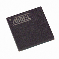
T89C51CC01CA-7CTIM Atmel, T89C51CC01CA-7CTIM Datasheet - Page 25

T89C51CC01CA-7CTIM
Manufacturer Part Number
T89C51CC01CA-7CTIM
Description
IC 8051 MCU FLASH 32K 64BGA
Manufacturer
Atmel
Series
AT89C CANr
Datasheets
1.T89C51CC01CA-7CTIM.pdf
(167 pages)
2.T89C51CC01CA-7CTIM.pdf
(12 pages)
3.T89C51CC01CA-7CTIM.pdf
(32 pages)
4.T89C51CC01CA-7CTIM.pdf
(29 pages)
Specifications of T89C51CC01CA-7CTIM
Core Processor
8051
Core Size
8-Bit
Speed
40MHz
Connectivity
CAN, UART/USART
Peripherals
POR, PWM, WDT
Number Of I /o
34
Program Memory Size
32KB (32K x 8)
Program Memory Type
FLASH
Eeprom Size
2K x 8
Ram Size
1.25K x 8
Voltage - Supply (vcc/vdd)
3 V ~ 5.5 V
Data Converters
A/D 8x10b
Oscillator Type
External
Operating Temperature
-40°C ~ 85°C
Package / Case
64-BGA
For Use With
AT89STK-06 - KIT DEMOBOARD 8051 MCU W/CAN
Lead Free Status / RoHS Status
Contains lead / RoHS non-compliant
Other names
T89C51CC01CA7CTIM
Available stocks
Company
Part Number
Manufacturer
Quantity
Price
Erase Flash
Start Bootloader
4211C–CAN–03/08
The T89C51CC01 flash memory is divided in several blocks:
Block 0: from address 0000h to 1FFFh
Block 1: from address 2000h to 3FFFh
Block 2: from address 4000h to 7FFFh
These three blocks contain 128 pages.
•
•
Note:
This routine allows to start at the beginning of the bootloader as after a reset. After calling this
routine the regular boot process is performed and the communication must be opened before
any action.
•
•
•
Parameter settings
instruction: LCALL FFF0h.
No special parameter setting
Set bit ENBOOT in AUXR1 register
instruction: LJUMP or LCALL at address F800h
__api_erase_block0
__api_erase_block1
__api_erase_block2
1. See the T89C51CC01 data sheet for the time that a write operation takes and this time must
2. No special resources are used by the bootloader during these operations
multiply by the number of pages.
API name
T89C51CC01 UART Bootloader
01h
R1
DPTR0
0000h
2000h
4000h
DPTR1
x
x
x
Acc
x
x
x
25


